Enhancing 3GPP R16 BDT for AIML Functionality
Learn about enhancing 3GPP R16 BDT to accommodate AIML functions through a proposed enhancement. Explore the background of 3GPP data transfer and negotiation, along with potential enhancements for future papers. The process involves steps for negotiation, translation, policy control, and activation of background data transfer. Discover how the BD PCF, NEF, UDR, and other entities collaborate to facilitate efficient data transfer in a telecom network.

Download Presentation

Please find below an Image/Link to download the presentation.
The content on the website is provided AS IS for your information and personal use only. It may not be sold, licensed, or shared on other websites without obtaining consent from the author. If you encounter any issues during the download, it is possible that the publisher has removed the file from their server.
You are allowed to download the files provided on this website for personal or commercial use, subject to the condition that they are used lawfully. All files are the property of their respective owners.
The content on the website is provided AS IS for your information and personal use only. It may not be sold, licensed, or shared on other websites without obtaining consent from the author.
E N D
Presentation Transcript
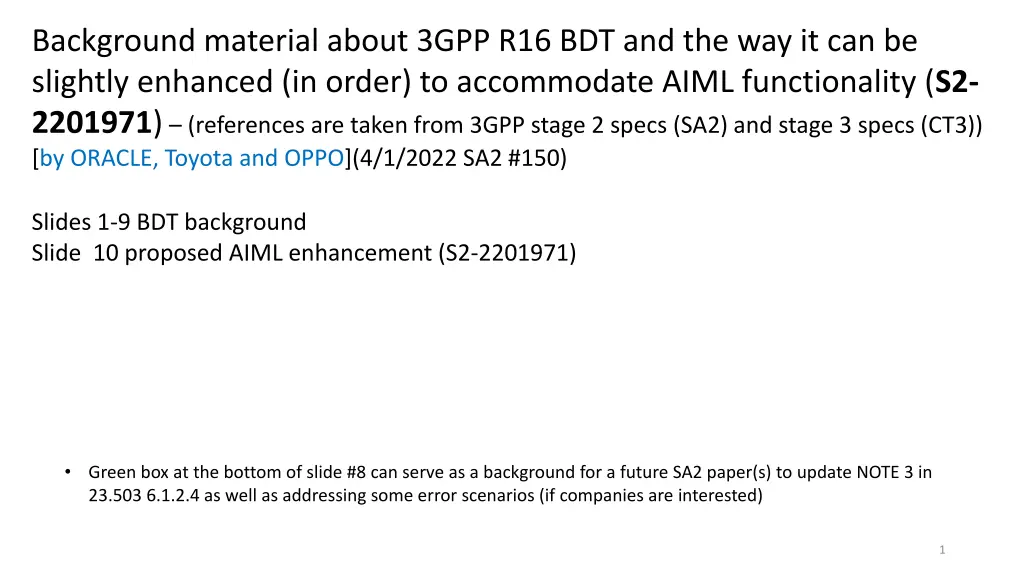
Background material about 3GPP R16 BDT and the way it can be slightly enhanced (in order) to accommodate AIML functionality (S2- 2201971) (references are taken from 3GPP stage 2 specs (SA2) and stage 3 specs (CT3)) [by ORACLE, Toyota and OPPO](4/1/2022 SA2 #150) Slides 1-9 BDT background Slide 10 proposed AIML enhancement (S2-2201971) Green box at the bottom of slide #8 can serve as a background for a future SA2 paper(s) to update NOTE 3 in 23.503 6.1.2.4 as well as addressing some error scenarios (if companies are interested) 1
3GPP background 3GPP background data transfer data transfer Initial BDT negotiation (23.502 Figure 4.16.7.2-1) The BD PCF would be a PCF, which supports BDT negotiation functionality. This BD PCF needs to register itself in the (PLMN Level) NRF with BDT svc (29.510 NFProfile.nfServices will include BDT svc), so that NEF can find it in step 2 above. UDR AF BD-PCF NEF 1Nnef_BDTPNegotiation_Create request 2Npcf_BDTPolicyControl_Create request 3. Nudr_DM_Query request 4. Nudr_DM_Query response N33 29.522 => T8 29.122 Step 2: If External Group Identifier is provided, The NEF translates the External Group Identifier into the Internal Group Identifier using Nudm_SDM_Get (Group Identifier Translation, External Group Identifier)(see 23.502 Table 5.2.3.3.1-4 or/and 29.503 5.2.2.2.14). . Policy decision 6Npcf_BDTPolicyControl_Create 7Nnef_BDTPNegotiation_Create response response 8 Nnef_BDTPNegotiation_Update request 9Npcf_BDTPolicyControl_Update request NEF then invokes the Npcf_BDTPolicyControl_Create (ASP id, Number of UEs, Volume per UE, Desired time window and optionally Internal Group Identifier, the Network Area Information, Request for notification) [23.503 6.1.2.4 : ASP-id may get mapped to S-NSSAI/DNN either by NEF or by BD PCF] . 10 Npcf_BDTPolicyControl_Update response Nnef_BDTPNegotiation_Update 11 response 12 Nudr_DM_Update request Nudr_DM_Update response 13 Step 3: The BD PCF may request from the UDR the stored transfer policies for all the ASPs using Nudr_DM_Query (Policy Data, Background Data Transfer) service operation. 23.502 Figure 4.16.7.2-1: Negotiation for future background data transfer BDT ref id is generated by the BD-PCF as pat of step 2. It is stored in the UDR in step 12. The REF ID generated by the PCF must be correlated with the individual UE entry Background Data Transfer Reference ID(s)(23.503 Table 6.2-2) see next slide. (since PCF may use it to admit PDU session with DNN=BDT.) Later on (C3-195251 (29.525)) as part of AF future activation of BDT, the AM PCF shall use the S-NSSAI and DNN associated with the ASP-id to store in the UDR the Background Data Transfer Reference ID(s) in the UE's session management policy data as specified in 3GPP TS 29.519 (area 3 in slide #4). AM-PCF receives internal-grp-id or a SUPI (29.507/29.525) and matches it against grp-id received during activation of BDT. Step 4: The UDR provides all the stored transfer policies and corresponding related information (ASP identifier, transfer policy, Background Data Transfer Reference ID, volume of data to be transferred per UE, expected amount of UEs, optionally a maximum aggregated bitrate subscription to notifications when the BDT policy needs to renegotiated) As per 23.503 6.1.2.4 State: BDT is negotiated for anonymous group for an ASP. It is identified by BDT Ref ID
BDT activation, Alternative 1 (future PDU Sessions): Close to actual BDT transfer time (eg 1 minute before data transfer negotiated time), AF/NEF apply the negotiated BDT policy to a specific group of UEs. This gets stored by the NEF in the UDR in Application data.BDT (Internal Group Identifier or SUPI used as a key)(UDR BDT Area 1(see slide #4)). AM PCF (29.525) (and potentially SM PCF as well (29.512)) had subscribed to UDR notification ahead of time (eg AM PCF instantiation). Consequently, UDR notifies AM PCF (internal grp id or supi)(and potentially SM PCF as well). For each individual SUPI in the group: 1. AM PCF stores BDT Ref-ID in PDU Session related of user profile in the UDR(UDR BDT Area 3(see slide #4))(29.525 5.6.2.3 AM PCF receives from the AMF the List of Internal Group Identifiers of the served UE). 2. AM PCF updates URSP BDT entry (APP->S-NSSAI/DNN/Location/Time) both in the UDR and at the UE (via configuration update procedure (UE obviously needs to be registered for that to happen)). Very close to actual BDT transfer time (eg 1 second before data transfer), each UE in the BDT ASP group will (based on the BDT URSP entry) automatically invoke the BDT app (ie no user involvement). It will request establishment of PDU Session on BDT S- NSSAI/DNN. SM PCF will admit or reject the PDU Session establishment request based on the Policy Data.PDU Session policy control data at the UDR (Area 3). SM PCF will allocate QoS/charging based on the BDT policy decision (see slide #6 - BdtData and TransferPolicy)(ie SM PCF looks up UDR in area 3 first(to learn what BDT is allowed/associated for/with the UE) and then in area 2) BDT activation, Alternative 2 (existing PDU Sessions) (equivalent to the 4G way of BDT activation): UE will establish PDU Session, which can either accommodate BDT or is dedicated to BDT (It may have for example a provisioned URSP entry for BDT with S-NSSAI/DNN info (but possibly without time/location info)). AF/NEF via N5 will ask to activate BDT transfer for the UE (BDT Ref ID is provided as a handle). AF/NEF will present BDT Ref ID. PCF will match it against Area 2 in the UDR(slide #4) (Policy Data.BDT data). See 29.514 5.6.2.3 AppSessionContextReqData.bdtRefId . 3
Attribute name Data type P 29.519 6.4.2.7 (UDR) DB aspects of BDT: interGroupId GroupId O 23.502 Table 5.2.12.2.1-1: Data keys, there are three different areas in the UDR where BDT information is stored: supi Supi O bdtRefId BdtReferenceId M dnn Dnn O Area 1. Application data.BDT (Internal Group Identifier or SUPI used as a key)(updated by NEF as a result of applying the BDT Policy to a future session procedure) snssai Snssai O NOTE: Either "supi" or "interGroupId" shall be included. Application data Packet Flow Descriptions (PFDs) AF traffic influence request information (See clause 5.6.7 and clause 6.3.7.2 in TS 23.501 [2]). Background Data Transfer (NOTE 3) (future activation) Service specific information (See clause 4.15.6.7) UE context policy control data (See clause 6.2.1.3 in TS 23.503 [20]) PDU Session policy control data (See clause 6.2.1.3 in TS 23.503 [20]) (future activation) Policy Set Entry data (See clause 6.2.1.3 in TS 23.503 [20]) Area 2. Policy Data.BDT data (BDT Reference ID used as a key for updating sake (no key for retrieval)) (updated by BDT PCF as a result of BDT negotiation procedure) Area 3. Policy Data.PDU Session policy control data (BDT Ref ID)) (SUPI/S- NSSAI/DNN used as a key)(updated by AM PCF as a result of applying the BDT Policy to a future session procedure. Retrieved by SM PCF (content=BDT Ref ID))(Later on when the UE sends PDU Session Establishment request, the SMF/PCF will be able to perform session admission based on that (eg is the UE using the proper BDT S-NSSAI/DNN.. Is it the proper time for the UE to establish the session, is it the right location)) Policy Data Area 3 Remaining allowed Usage data (See clause 6.2.1.3 in TS 23.503 [20]) Sponsored data connectivity profiles (See clause 6.2.1.6 in TS 23.503 [20]) Background Data Transfer data (See clause 6.2.1.6 in TS 23.503 [20]) (negotiation) Area 2 23.502 Table 5.2.12.2.1-1: Data keys
Area #1 in the UDR (Future activation) Applicability Attribute name Data type P Cardinal ity O 0..1 Description GroupId Identifies a group of users. (NOTE) Identifies a user. (NOTE) Identifies a selected policy of background data transfer. Identifies a DNN The identification of slice. Represents the URI of Individual Applied BDT Policy Data. It shall only be included in the HTTP GET response. interGroupId supi bdtRefId Supi BdtReferenceI d Dnn Snssai Uri O 0..1 M 1 dnn snssai resUri O 0..1 O 0..1 C 0..1 S-NSSAI/DNN would probably be included only if they had not been provided earlier during the BDT negotiation ( in Area 2). NOTE: Either "supi" or "interGroupId" shall be included. 29.519 Table 6.4.2.7-1: Definition of type BdtPolicyData = Area #1 in slide 4 UE subscription (aka UE Profile) for UE/S-NSSAI/DNN 5
Area #2 in the UDR (negotiated BDT) 3GPP background 3GPP background data transfer data transfer BEFORE our paper 29.519 Table 5.4.2.9-1: BdtData 29.554 Table 5.6.2.5-1: Definition of type TransferPolicy Attribute name aspId Data type P M 1 Cardinality Description Attribute name maxBitRateDl BitRate Data type P O Cardinality 0..1 Description string This IE contains an identity of an application service provider. This IE contains the transfer policy. This IE indicates the background data transfer reference ID for the transfer policy. This IE represents a network area information. This IE indicates a maximum aggregated(*) bitrate in the downlink direction authorized by the PCF. This IE indicates a maximum aggregated(*) bitrate in the uplink direction authorized by the PCF. This IE indicates a rating group for the recommended time window. This IE indicates a recommended time window of a transfer policy. This IE contains an identity of a transfer policy. transPolicy bdtRefId M 1 O 0..1 TransferPolicy BdtReferenceId nwAreaInfo NetworkAreaInf o Uinteger O 0..1 maxBitRateUl BitRate O 0..1 numOfUes O 0..1 This IE contains the number of UEs using the indicated transfer policy. It shall be present when available. This IE contains a data volume expected to be transferred per UE for the indicated transfer policy. It shall be present when available. This IE identifies a DNN. This IE identifies a slice. Contains the traffic descriptor of the background data. Contains the validation status for a negotiated BDT policy. It shall be included when available. Default value is "VALID" if omitted. volPerUe UsageThreshold O 0..1 ratingGroup integer M 1 dnn snssai trafficDes Dnn Snssai TrafficDescriptor O 0..1 O 0..1 O 0..1 recTimeInt TimeWindow M 1 transPolicyId integer M 1 bdtpStatus BdtPolicyStatus O 0..1 (*) Aggregated = overall Bit Rate for the entire group [Oracle/Toyota/OPPO]: when the PDU session is active and pcc rules are sent to the SMF, each of the UEs in the BDT group may be handled by a diff PCF, diff SMF and diff UPF. Consequently it may be reasonable to assume that each UE will get: <max bitrate = the overall aggregated max bitrate divided by number of UEs> (since there is currently no coordination mechanism between the various PCFs) 6
Area #3 in the UDR (Future activation) Attribute name Data type P M O O O O O Cardinality Description dnn allowedServices subscCats gbrUI gbrDl adcSupport Dnn array(string) array(string) BitRate BitRate boolean 1 1..N 1..N 0..1 0..1 0..1 DNN associated with the data List of subscriber's allowed service identifiers List of categories associated with the subscriber Maximum aggregate UL bitrate that can be provided across all GBR QoS Flows in the DNN Maximum aggregate DL bitrate that can be provided across all GBR QoS Flows in the DNN Indicates whether application detection and control can be enabled for a subscriber. The default value is "FALSE". Indicates whether the PCF must enforce policies based on subscriber spending limits. The default value is "FALSE". Information that identifies which IP pool or external server is used to allocate the IPv4 address. Information that identifies which IP pool or external server is used to allocate the IPv6 address. Indicates the offline charging is applicable to the PDU session. The default value is "FALSE". Indicates the online charging is applicable to the PDU session. The default value is "FALSE". The address(es) and, if available, the CHF instance ID and the CHF set ID of the Charging Function. (NOTE) A reference to the "UsageMonitoringDataLimit" or "UsageMonitoringData" instances for this DNN and SNSSAI that may also include the related monitoring key(s). The key of the map is the limit identifier. Indicates subscription to the MPS priority service; priority applies to all traffic on the PDU Session. The default value is "FALSE". Indicates subscription to the MCS priority service; priority applies to all traffic on the PDU Session. The default value is "FALSE". Indicates subscription to the IMS signalling priority service; priority only applies to IMS signalling traffic. The default value is "FALSE". Relative priority level for the multimedia priority services Relative priority level for the mission critical services Presence reporting area information. Each PresenceInfo element shall include the Presence Reporting Area Identifier within the "praId" attribute and, for a UE-dedicated presence reporting area, may also include the list of elements composing the presence reporting area. A "praId" may indicate a Presence Reporting Area Set. The "praId" attribute within the PresenceInfo data type shall also be the key of the map. The attribute "presenceState" shall not be present. Identifies transfer policies of background data transfer. Any string value can be used as a key of the map. Identifies whether AF influence on traffic routing is allowed or not. Set to "true" if no local routing is allowed; otherwise set to "false". The default value is "false". subscSpendingLimits boolean O 0..1 ipv4Index ipv6Index offline online chfInfo IpIndex IpIndex boolean boolean ChargingInformation O O O O O 0..1 0..1 0..1 0..1 0..1 refUmdLimitIds map(LimitIdToMonitoringKey) O 1..N mpsPriority boolean O 0..1 mcsPriority boolean O 0..1 imsSignallingPrio boolean O 0..1 mpsPriorityLevel mcsPriorityLevel praInfos integer integer map(PresenceInfo) O O O 0..1 0..1 1..N bdtRefIds map(BdtReferenceIdRm) O 1..N locRoutNotAllowed boolean O 0..1 29.519 Table 5.4.2.15-1: Definition of type SmPolicyDnnData = Area #3 in slide 4 UE subscription (aka UE Profile) for UE/S-NSSAI/DNN 7
umId string M 1 Contains the Usage Monitoring ID, which univocally identifies the usage monitoring policy data instance within a PDU session. (NOTE) Indicates the total volume threshold. Indicates a volume threshold in uplink. Indicates a volume threshold in downlink. Indicates a time threshold. Attribute name qosId Data type P M Cardinality 1 Description string Univocally identifies the QoS control policy data within a PDU session. Identifier for the authorized QoS parameters for the service data flow. It shall be included when the QoS data decision is initially provisioned and "defQosFlowIndication" is not included or is included and set to false. Indicates the maximum bandwidth in uplink. Indicates the maximum bandwidth in downlink. Indicates the guaranteed bandwidth in uplink. (NOTE 3) Indicates the guaranteed bandwidth in downlink. (NOTE 3) Indicates the allocation and retention priority. It shall be included when the QoS data decision is initially provisioned and "defQosFlowIndication" is not included or is included and set to false. 5qi 5Qi C 0..1 volumeThreshol d volumeThreshol dUplink volumeThreshol dDownlink timeThreshold VolumeRm O 0..1 VolumeRm O 0..1 VolumeRm O 0..1 maxbrUl BitRateRm O 0..1 DurationSec Rm DateTimeR m O 0..1 maxbrDl BitRateRm O 0..1 monitoringTime O 0..1 Indicates the time at which the UP function is expected to reapply the next thresholds (e.g. nextVolThreshold). gbrUl BitRateRm O 0..1 gbrDl BitRateRm O 0..1 29.512 Table 5.6.2.12-1: Definition of type UsageMonitoringData only the first few attributes arp Arp C 1 23.503 6.1.2.4 NOTE 3: (optionally provided in a BDT policy) is not enforced in the network. The operator may apply offline CDRs processing (e.g. combining the accounted volume of the involved UEs for the time window) to determine whether the maximum aggregated bitrate for the set of UEs was exceeded by the ASP and charge the excess traffic differently. The maximum aggregated bitrate 29.512 Table 5.6.2.8-1: Definition of type QosData only the first few attributes [Oracle/Toyota/OPPO] 29.512 SmPolicyDecision does not include BDT ref ID on any level. In other words SMF/UPF does not learn from the PCF that a specific PDU Session of UE x is associated with some BDT group. SMF/UPF needs to enforce the SmPolicyDecision exactly as received from the PCF. So basically the above NOTE 3 is informative and may be *overwritten* by the PCC rules.. We did not indicate that the same SM PCF should be selected for all of the UEs in the BDT group, so every SM PCF is basically free to install any pcc rules for the BDT traffic based on the negotiated BDT policy (btw, in general, NOTEs in SA2 specs are informative/clarifications/assumptions). 8
[Oracle/Toyota/OPPO] A question: What if a UE in the BDT group uses an existing PDU Session for the download/upload of BDT info? Answer: If the S-NSSAI/DNN of that PDU Session does not match the negotiated S-NSSAI/DNN, this should probably be considered & handled as an error scenario, since it defeats the whole idea behind BDT negotiation and activation Otherwise, (S-NSSAI/DNN matches) then either the SM PCF should receive a corresponding BDT activation request over N5 or it may receive a notification from the UDR about BDT activation for the associated group of UEs. NOTE: depends on the agreement between the operator and the BDT ASP a BDT activation may be invoked via UDR or directly over N5. In the former case (UDR), it means SM PCF should subscribe to BDT activation notifications at the UDR for any user who might be associated with BDT (this association might be defined in the subscriber profile in the UDR as part of either SubsCategory or Allowed Services (see 29.519 Table 5.4.2.15-1 in slide #7)) This should immediately trigger the SM PCF to push down to the SMF BDT related PCC rules (ie it shall be viewed by the SM PCF as if it has just received a request for BDT related dedicated QoS Flows now). Before the expected (ie negotiated) BDT transfer time (ie user plane action), the PCF can install pcc rules to block (or throttle) BDT related traffic (Slide #6 Area #2 in the UDR has TrafficDescriptor). When BDT transfer starts, the PCF can temporarily remove the blocking rules. After BDT time the PCF can re-install the blocking pcc rules (or even trigger a release of the PDU session). Above is the Answer for how to handle BDT for existing PDU Sessions 9
Grey area Below (Right Bottom) shows how BDT negotiated policy may look like, after S2-2201971 had updated it (stage 3 ref. are for illustration purpose only). Attribute name maxBitRateDl Data type BitRate P O Cardinality 0..1 Description This IE indicates a maximum aggregated(*) bitrate in the downlink direction authorized by the PCF. This IE indicates a maximum aggregated(*) bitrate in the uplink direction authorized by the PCF. This IE indicates a rating group for the recommended time window. This IE indicates a recommended time window of a transfer policy. This IE contains an identity of a transfer policy. Attribute name aspId Data type P M 1 Cardinality Description string This IE contains an identity of an application service provider. This IE contains the transfer policy. This IE indicates the background data transfer reference ID for the transfer policy. This IE represents a network area information. This IE contains the number of UEs using the indicated transfer policy. It shall be present when available. This IE contains a data volume expected to be transferred per UE for the indicated transfer policy. It shall be present when available. This IE identifies a DNN. This IE identifies a slice. Contains the traffic descriptor of the background data. Contains the validation status for a negotiated BDT policy. It shall be included when available. Default value is "VALID" if omitted. transPolicy bdtRefId M 1 O 0..1 TransferPolicy BdtReferenceId maxBitRateUl BitRate O 0..1 nwAreaInfo numOfUes NetworkAreaInfo Uinteger O 0..1 O 0..1 ratingGroup integer M 1 volPerUe UsageThreshold O 0..1 recTimeInt TimeWindow M 1 dnn snssai trafficDes bdtpStatus Dnn Snssai TrafficDescriptor BdtPolicyStatus O 0..1 O 0..1 O 0..1 O 0..1 transPolicyId integer M 1 Packet Delay Budget for UL integer O 0..1 This IE indicates Packet Delay Budget for UL equally for any UE in the BDT group Packet Delay Budget for DL integer O 0..1 This IE indicates Packet Delay Budget for DL equally for any UE in the BDT group 29.519 Table 5.4.2.9-1: BdtData Maximum Data Burst Volume for UL integer O 0..1 This IE indicates Maximum Data Burst Volume for UL equally for any UE in the BDT group AFTER our paper (Grey cells are the AIML additions) 29.554 Table 5.6.2.5-1: Definition of type TransferPolicy (when SM PCF installs pcc rules based on the Transfer policy, it may wrap up the new 6 QCI attributes in a 5QI (This 5QI may be either a dynamic one or a standardized one)) In the case when Packet Delay Budget per UE, Packet Error Rate per UE and Maximum Data Burst Volume for per UE are asymmetric for UL and DL directions, two PCC rules will have to be provided by the PCF. Each PCC rule will be for each direction (ie UL or DL). Each PCC rule will have its own 5QI and the corresponding TFTs.) Maximum Data Burst Volume for DL integer O 0..1 This IE indicates Maximum Data Burst Volume for DL equally for any UE in the BDT group Packet Error Rate for UL integer O 0..1 This IE indicates Packet Error Rate for UL equally for any UE in the BDT group Packet Error Rate for DL integer O 0..1 This IE indicates Packet Error Rate for DL equally for any UE in the BDT group 10


:")

")
")
")


 shows how BDT negotiated")