Epidemiology and Population Screening
Infectious diseases, control methods, antimicrobial resistance, disease surveillance, and the impact of environmental changes on disease patterns are discussed in the field of epidemiology.

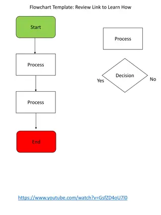
Download Presentation

Please find below an Image/Link to download the presentation.
The content on the website is provided AS IS for your information and personal use only. It may not be sold, licensed, or shared on other websites without obtaining consent from the author.If you encounter any issues during the download, it is possible that the publisher has removed the file from their server.
You are allowed to download the files provided on this website for personal or commercial use, subject to the condition that they are used lawfully. All files are the property of their respective owners.
The content on the website is provided AS IS for your information and personal use only. It may not be sold, licensed, or shared on other websites without obtaining consent from the author.
E N D
Presentation Transcript
CHAPTER 3 Cross Moment Distribution Method
Moment Distribution Iterative Method Directly computes End Moments. Convenient for small to medium sized problems
Concepts SIGN CONVENTION = CLOCKWISE MOMENTS on the MEMBER are considered as POSITIVE. FIXED END MOMENTS
Concepts Member Stiffness Factor:- defined as the magnitude of moment M req d to rotate end A by 1 rad. The moment M is computed as The member stiffness factor is defined as the term in the brackets.
Concepts Joint Stiffness Factor:- The total amount of moment needed to rotate a joint by 1 rad.
Concepts Distribution Factor:- If a moment is applied to a fully connected fixed joint, then this moment is distributed to each connected member depending on each member s stiffness. The distribution factor is such a percentage/ratio computed for each member.
Concepts Member relative stiffness factor:- As E is usually constant for a structure, the stiffness for a single member can be defined as : We use this value to compute the distribution factor.
Concepts Carry-Over Factor:- For a rotation of 1 rad , We ve seen that M= (4EI/L) a and M = (2EI/L) a In other words, M =(1/2)M. The carry-over factor represents the fraction of M carried-over from the pin to the wall.( In this case +1/2)
Moment Distribution for Beams Examples
Stiffness Factor Modifications Member Pin Supported at Far End:- Symmetric Geometry + Loading:- Symmetric Geometry + Anti-symmetric Loading:-
Example (Cont.) M. Distribution Table
M. Distribution for Frames: NO Sidesway Example Joints E and D are pinned while A is fixed.
Example (Frame NO-Sidesway) Stiffness Factors Fixed End Moments
Example (Frame NO-Sidesway) Distribution Factors
Example (Frame NO-Sidesway) Distribution Table
Example (Frame NO-Sidesway) Moment Diagram
Frames (Sidesway) Step one: Place an artificial joint to prevent sway and analyze the structure to get the imaginary reaction R
Frames (Sidesway) Step two: Assume an equal and opposite force, R, is applied at the previous joint causing the structure to sway by a certain horizontal displacement d.
Frames (Sidesway) For a certain assumed value of d, resulting end moments as well as R can be computed. These magnitudes are proportional to the values developed in step one (Hooke s law). Hence, the final end moment is the sum of the original non-sway moments and a proportional (R/R ) magnitude of the sway moments.
Example: Frames (Sidesway) Step One:
Example: Frames (Sidesway) Fixed End Moments
Example: Frames (Sidesway) Step One: R= Ax+Dx= -(1.73-0.81) = -0.92 kN
Example: Frames (Sidesway) Step two: Assume the virtual force causes the following FEMS
Example: Frames (Sidesway) R = -(Ax+Dx) = -(28+28) =56 KN
Example: Frames (Sidesway) The actual moment values caused by the sway force R are computed by taking the proportioned values of the end moments computed for R . M = (R/R ) * M M = (1.92/56) * M
Example: Frames (Sidesway) Total Moments = M(Non-sway) +( R/R )*M (Sway)


")
")

")
")
")
")
")
")
")
")
")
")
")
")
")
")
")
")
")