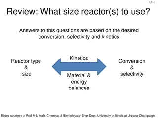
Equilibrium Conversion and Temperature Optimization in Chemical Reactions
Explore the principles of equilibrium conversion and temperature optimization in chemical reactions, covering topics such as endothermic and exothermic reactions, Le Chatelier's principle, and interstage cooling. Understand how feed temperature impacts reaction rates and conversion efficiency, guiding you to maximize reaction yields.

Download Presentation

Please find below an Image/Link to download the presentation.
The content on the website is provided AS IS for your information and personal use only. It may not be sold, licensed, or shared on other websites without obtaining consent from the author. If you encounter any issues during the download, it is possible that the publisher has removed the file from their server.
You are allowed to download the files provided on this website for personal or commercial use, subject to the condition that they are used lawfully. All files are the property of their respective owners.
The content on the website is provided AS IS for your information and personal use only. It may not be sold, licensed, or shared on other websites without obtaining consent from the author.
E N D
Presentation Transcript
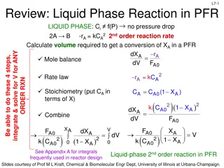
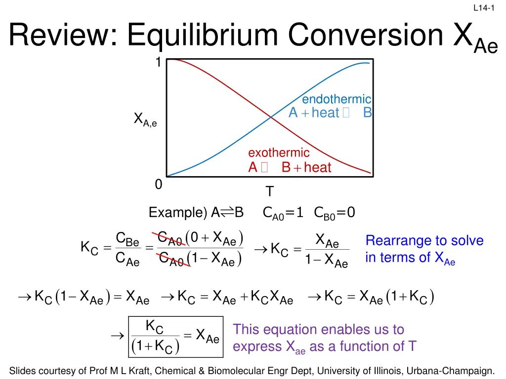
L14-1 Review: Equilibrium Conversion XAe 1 endothermic heat + A B XA,e exothermic + A B heat 0 T Example) A B CA0=1 CB0=0 ( ) ( ) A0 Ae C 1 X + C 0 X C C X Rearrange to solve in terms of XAe A0 Ae Be Ae = = K = K C C 1 X Ae Ae ( ) ( ) = 1 K + = + 1 X = K X K X K X K X C Ae C C Ae C Ae C Ae Ae K + This equation enables us to express Xae as a function of T C = X Ae ( ) 1 K C Slides courtesy of Prof M L Kraft, Chemical & Biomolecular Engr Dept, University of Illinois, Urbana-Champaign.
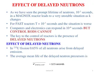
L14-2 Review: XAe and Temperature X H 1 exp K T material 1 = Ae ( ) T 1 T 1 RX R R + 1 ( ) T Clicker question C 2 2 ( ) H T 1 T 1 ( ) RX R R Exothermic & C =0: H T 0 , when T e xp & X P RX R Ae T 2 + A B heat Makes sense from Le Chatelier s principle Exothermic rxn produces heat increasing temp adds heat (product) & pushes rxn to left (lower conversion) ( ) H T 1 T 1 ( ) RX R R Endothermic & C 0: H T 0 , when T exp & X p R X R Ae T 2 + A heat B Makes sense from Le Chatelier s principle Heat is a reactant in an endothermic rxn increasing temp adds reactant (heat) & pushes rxn to right (higher conversion) Slides courtesy of Prof M L Kraft, Chemical & Biomolecular Engr Dept, University of Illinois, Urbana-Champaign.
L14-3 Review: Optimum Feed Temperature For reversible, exothermic rxns, optimize feed temperature to maximize XA High T0: moves XA,EB line to the right. Rxn reaches equilibrium fast, but low XA Low T0 would give high XA,e but the specific reaction rate k is so small that most of the reactant passes through the reactor without reacting (never reach XA,e) From thermodynamics XEB XA 0.75 T0 = 500 0.33 T0 = 600 T0 = 350 0.15 600 350 500 T W Slides courtesy of Prof M L Kraft, Chemical & Biomolecular Engr Dept, University of Illinois, Urbana-Champaign.
L14-4 Review: Interstage Cooling Adiabatic operation of each reactor simplifies the energy balance Higher feed temp- reaction reaches equilibrium quickly but XA,e is low Lower feed temp- higher XA,e but reaction rate is too slow to be practical Cooling between reactors shifts XA,EB line to the left, increasing XA XA,EB4 XEB XA,EB3 final conversion Each reactor operates adiabatically XA,EB2 XA,EB1 cooling process T Cooling, C1 C2 C3 T0 Reactor 1 Reactor 2 Reactor 3 Reactor 4 Slides courtesy of Prof M L Kraft, Chemical & Biomolecular Engr Dept, University of Illinois, Urbana-Champaign.
L14-5 Review: Endothermic Reactions The equilibrium conversion increases with increasing temperature, so use interstage heating to increase the conversion XEB final conversion Red lines are from the energy balance, slant backwards because H RX >0 for endothermic reaction heating process T Slides courtesy of Prof M L Kraft, Chemical & Biomolecular Engr Dept, University of Illinois, Urbana-Champaign.
L14-6 L14: Nonadiabatic PFR/PBR Operation and Reactor Stability 1. T changes with distance down reactor- differential form of EB must be used Multiple steady states: more than one set of conditions satisfies both the energy balance & mole balance 2. Slides courtesy of Prof M L Kraft, Chemical & Biomolecular Engr Dept, University of Illinois, Urbana-Champaign.
L14-7 Review: Application to a SS PFR FA0 FA XA T distance Negligible shaft work ( S=0) and adiabatic (Q=0) a) b) c) d) Use TEB to construct a table of T as a function of XA Use k = Ae-E/RT to obtain k as a function of XA Use stoichiometry to obtain rA as a function of XA Calculate: XA A0 XA0 dX may use numerical methods A = V F ( ) r X ,T A A Slides courtesy of Prof M L Kraft, Chemical & Biomolecular Engr Dept, University of Illinois, Urbana-Champaign.
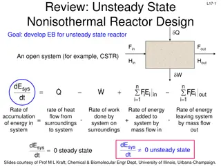
Steady-State PFR/PBR w/ Heat Exchanger L14-8 Heat is added or removed through the cylindrical walls of the reactor ( = a Q U A T Ta ) ( ) A V = T Ua T T V = a a FA0 Heat exchange area per volume of reactor FAe T i i FH i i FH T0 Te V+ V V Energy balance on small volume of SS PFR: + = Q W 0 i i FH i i FH 0 s + V V V ( ) + = Ua T T V W i i FH i i FH 0 Plug in Q: a s + V V V ( ) d i i F H dV ( ) = Take limit as V : a T U T 0 a dF dV dH dV ( ) i i = Ua T T H F 0 Expand: a i i Slides courtesy of Prof M L Kraft, Chemical & Biomolecular Engr Dept, University of Illinois, Urbana-Champaign.
L14-9 TEB for PFR/PBR w/ Heat Exchanger Ta FA0 FAe i i FH i i FH T T0 Te V+ V dF d V dF d V dH ( ) i i = Ua T T H FdV 0 a i i dH dV dT dV ( ) i i = = = r r an d C Substitute the differentials: i i A p i V d dV T ( ) ( ) = i = Ua T T H Ar F C 0 H H i i R X a i i Pi dT dV ( ) ( ) = Solve for dT/dV: Ua T T H r FC 0 a RX A i Pi ( ) ( ) + H r Ua T T dT dV dT dV RX A a ( ) ( ) = = i Pi FC H r Ua T T RX A a i Pi FC Slides courtesy of Prof M L Kraft, Chemical & Biomolecular Engr Dept, University of Illinois, Urbana-Champaign.
L14-10 Energy Balance for Tubular Reactors Heat removed Multiply Ua and (Ta-T) by -1 (-1 x -1 = 1) Heat generated Heat generated Heat removed ( ) ( ) ( ) ( ) + H r Ua T T H r Ua T C T dT dV dT dV RX A a R X A a = = F i Pi F C i Pi Switched sign & order in bracket ( ) = + ) H H (T ) C T T Substitute and multiply out the denominator RX = RX R P R ( + F F X i A0 i i A for A B ( ) ( ) ( C ) + + H (T ) C T T r Ua T T b a dT dV RX R P R A X a i Pi C = = C C C = PB PA P ( ) + F C A0 i Pi Pi i A ( ) ( ) ( C ) + + H (T ) C T T r Ua T T Energy balance for SS PFR, s=0 dT d V RX R P R + A X a = ( ) F i P C A0 i P A dX dV r PFR energy balance is coupled to the PFR design eq, and PFR design eq is coupled to Arrhenius eq for k or Kequil (these are the 3 equations that must be simultaneously solved) A A = F A0 Slides courtesy of Prof M L Kraft, Chemical & Biomolecular Engr Dept, University of Illinois, Urbana-Champaign.
L14-11 Liquid Phase Reaction in PFR B liquid phase rxn carried out in PFR; W = A 0 & pure A enters the PFR S dX dV r A A = Mole balance F A0 H C B = r k C with Rate law A A K C ( ) T 1 1 T E R T 1 1 T ( ) T ( ) RX R R = K K T exp = k k exp C C 2 1 T 2 1 = (1 X ) = C C C C X Stoichiometry A A0 A B A0 A k 1 X X K dX dV A A C A = Combine ) ( C X + 0 ( ) ( ) + + H (T ) C T T r Ua T T dT dV RX R P R A a Energy balance = ( ) i Pi C F A0 P A Solve these equations simultaneously with an ODE solver (Polymath) If this were a gas phase rxn w/ pressure drop, change stoichiometry accordingly & include an equation for d P/dW Slides courtesy of Prof M L Kraft, Chemical & Biomolecular Engr Dept, University of Illinois, Urbana-Champaign.
L14-12 Review: Nonisothermal CSTR Isothermal CSTR: feed temp = temperature inside the CSTR Case 1: Given FA0, CA0, A, E, Cpi, H I, and XA, calculate T & V a) b) c) Solve TEB for T at the exit (Texit = Tinsidereactor) Calculate k = Ae-E/RT where T was calculated in step a Plug the k calculated in step b into the design equation to calculate VCSTR Case 2: Given FA0, CA0, A, E, Cpi, H I, and V, calculate T & XA a) b) c) Solve TEB for T as a function of XA Solve CSTR design equation for XA as a function of T (plug in k = Ae-E/RT ) Plot XA,EB vs T & XA,MB vs T on the same graph. The intersection of these 2 lines is the conditions (T and XA) that satisfies the energy & mass balance XA,EB = conversion determined from the TEB equation XA,MB = conversion determined using the design equation XA,exit XA,MB Intersection is T and XA that satisfies both equations XA XA,EB T Texit Slides courtesy of Prof M L Kraft, Chemical & Biomolecular Engr Dept, University of Illinois, Urbana-Champaign.
L14-13 Multiple Steady States in CSTR 1 XA,EB XA,MB 0.8 0.6 XA 0.4 0.2 0 0 100 200 300 T (K) 400 500 600 Plot of XA,EB vs T and XA,MB vs T Intersections are the T and XA that satisfy both the mass balance and energy balance Multiple sets of conditions are possible for the same rxn in the same reactor with the same inlet conditions! Reactor must operate near one of these steady states- this requires knowledge of their stability! Slides courtesy of Prof M L Kraft, Chemical & Biomolecular Engr Dept, University of Illinois, Urbana-Champaign.
L14-14 Consider a jacketed CSTR with constant heat capacity, negligible shaft work, CP=0, first order kinetics, all feeds at the same temperature (Ti0=T0), constant Ta in jacket, and an overall heat transfer coefficient ( Q UA T = n A0 i p,i i 1 = Substituting for ( ) a Q UA T T and H = ) T a = TEB:0 Q F C T T H (T)F X i0 RX A0 A = = (T) H (T ) since C 0 RX RX R P n ( ) = i p,i C 0 UA T T F T T H (T )F X a A0 i0 RX R A0 A i 1 = Bring terms that remove heat to other side of equation: n ( ) i p,i C = F T T UA T T H (T )F X A0 i0 a RX R A0 A i 1 = ( F ) UA T T n a i p,i C = T T H (T )X i0 RX R A i 1 = A0 Heat removed term R(T) Heat generated term G(T) A steady-state occurs when R(T) = G(T) Slides courtesy of Prof M L Kraft, Chemical & Biomolecular Engr Dept, University of Illinois, Urbana-Champaign.
L14-15 Even More Terms Heat removed term R(T) Heat generated term G(T) ( F ) UA T T n a i p,i C = T T H ( T ) X i0 R X X r R A r V F r F = i 1 A 0 F A0 A A = = = V X C i Pi C A P0 A A 0 ( F ) UA T T V a A = C T T H ( T ) Substitute p 0 i0 RX R A0 A0 + 0 A0 p0 T F UA H = C + UAT UA + T 1 T a a 0 = = = T More substitutions: c p0 A0 C F + p0 A0 C F ( R T ) H RX RX r V ) ( A + = C 1 T T H p0 C RX F A0 Heat removed: Heat generated: r V F ( ) A ) = ( ) ( G T H = + R T C 1 T T RX p0 C A0 Slides courtesy of Prof M L Kraft, Chemical & Biomolecular Engr Dept, University of Illinois, Urbana-Champaign.
L14-16 Heat Removal Term and T0 Heat removed: R(T) Heat generated G(T) + T 1 T = a 0 UA C F = T r V F p 0 A 0 c ) ( A + + = C 1 T T H p0 C RX A0 = R(T) R(T) line has slope of CP0(1+ ) = 0 R(T) Increase For Ta < T0 Ta T0 T Increase T0 When increases from lowering FA0 or increasing heat exchange, slope and x-intercept moves T When T0 increases, slope stays same & line shifts to right Ta<T0: x-intercept shifts left as Ta>T0: x-intercept shifts right as =0, then TC=T0 = , then TC=Ta Slides courtesy of Prof M L Kraft, Chemical & Biomolecular Engr Dept, University of Illinois, Urbana-Champaign.
L14-17 CSTR Stability R(T) > G(T) so T gradually falls to T=SS3 G(T) > R(T) so T gradually rises to T=SS3 G(T) R(T) R(T) > G(T) so T gradually falls to T=SS1 3 G(T) & R(T) G(T) > R(T) so T gradually rises to T=SS1 2 1 Temperature T 3 steady states satisfy the TEB and BMB Suppose a disturbance causes the reactor T to drift to a T between SS1 & SS2 Suppose a disturbance causes the reactor T to drift to a T between SS2 & SS3 Suppose a disturbance causes the reactor T to drop below SS1 Suppose a disturbance causes the reactor T to rise above SS3 SS1 and SS3 are locally stable (return to them after temp pulse) SS2 is an unstable- do not return to SS2 if there is a temp pulse Slides courtesy of Prof M L Kraft, Chemical & Biomolecular Engr Dept, University of Illinois, Urbana-Champaign.
L14-18 Multiple Steady States and T0 R(T), G(T) T0,6 Increasing T above these TS cause a temperature jump to the higher TS T0,5 T0,4 T0,3 T0,2 T0,1 T TT Changing the inlet T will shift the steady state temperature (TS) Notice that the number of steady state temperatures depends on T0 Slides courtesy of Prof M L Kraft, Chemical & Biomolecular Engr Dept, University of Illinois, Urbana-Champaign.
L14-19 Temperature Ignition-Extinction Curve Slight increase in T above TS,green causes reactor T to jump to TS,cyan Ignition temp: T where jump from TS,lower to TS,upper occurs Slight decrease in T below TS,magenta causes reactor T to drop to TS,yellow Extinction temp: T where drop from TS,upper to TS,lower occurs R(T), G(T) TS,upper TS,lower T TS along dashed line are unstable Ts, steady-state temp Plot TS vs T0 Upper steady state Lower steady state ignition temperature extinction temperature T0, entering temperature Slides courtesy of Prof M L Kraft, Chemical & Biomolecular Engr Dept, University of Illinois, Urbana-Champaign.
L14-20 Runaway Reaction R(T), G(T) T Ignition temperature is very important: once T0 exceeds Tignition, transition to the upper steady state will occur undesirable dangerous Runaway reaction R(T) only intersects with upper steady state Slides courtesy of Prof M L Kraft, Chemical & Biomolecular Engr Dept, University of Illinois, Urbana-Champaign.