Exhaust and Carburetor Systems in Multi-Cylinder Engines
The exhaust system in multi-cylinder engines allows for optimized gas flow, while the carburetor arrangement ensures efficient fuel distribution. Learn how pressure pulses and wave interactions play a crucial role in enhancing engine performance.
Download Presentation

Please find below an Image/Link to download the presentation.
The content on the website is provided AS IS for your information and personal use only. It may not be sold, licensed, or shared on other websites without obtaining consent from the author.If you encounter any issues during the download, it is possible that the publisher has removed the file from their server.
You are allowed to download the files provided on this website for personal or commercial use, subject to the condition that they are used lawfully. All files are the property of their respective owners.
The content on the website is provided AS IS for your information and personal use only. It may not be sold, licensed, or shared on other websites without obtaining consent from the author.
E N D
Presentation Transcript
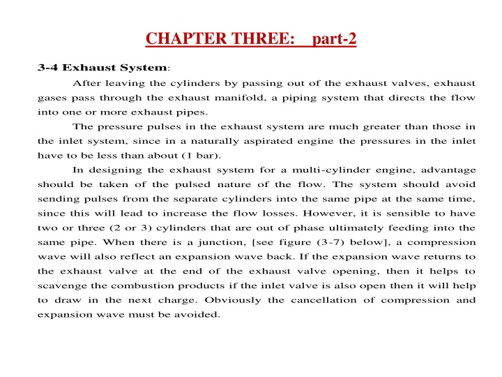
CHAPTER THREE: part-2 3-4 Exhaust System: gases pass through the exhaust manifold, a piping system that directs the flow into one or more exhaust pipes. The pressure pulses in the exhaust system are much greater than those in the inlet system, since in a naturally aspirated engine the pressures in the inlet have to be less than about (1 bar). In designing the exhaust system for a multi-cylinder engine, advantage should be taken of the pulsed nature of the flow. The system should avoid sending pulses from the separate cylinders into the same pipe at the same time, since this will lead to increase the flow losses. However, it is sensible to have two or three (2 or 3) cylinders that are out of phase ultimately feeding into the same pipe. When there is a junction, [see figure (3-7) below], a compression wave will also reflect an expansion wave back. If the expansion wave returns to the exhaust valve at the end of the exhaust valve opening, then it helps to scavenge the combustion products if the inlet valve is also open then it will help to draw in the next charge. Obviously the cancellation of compression and expansion wave must be avoided. After leaving the cylinders by passing out of the exhaust valves, exhaust
Compression Wave I n c r e a s i n g T i m e Expansion Wave Figure (3-7): Compression and Expansion Waves.
Example: Arrange the exhaust system for a 4-cylinder, 4-strokes engine having firing order [1-3-4-2]. Compression 1 1st junction 2nd junction 2 3 4 Exhaust Explanation: Consider the engine operating with the exhaust valve just opening on (cylinder- 1). A compression wave will travel to the first junction; since the exhaust valve on (cylinder-4) is closed, an expansion wave will be reflected back to the open exhaust valve. The same process occurs ( 180 ) later in the junction connecting cylinders (2 and 3). At the second junction, the flow is significantly steadier and ready for silencing.
3-5 Carburetor Arrangement for Multi-Cylinder: Inlet manifolds are usually designed for easy of production and assembly, even on turbocharged engines when a single carburetor per cylinder is used. The flow pulsation will cause a rich mixture at full throttle as the carburetor will feed fuel for flow in either direction. In engines with a carburetor supplying more than one cylinder, the flow at the carburetor will be steadier because the interaction between compression and expansion waves.
3-5-1 For Single Carburetor: Cylinders Cylinders 1 2 3 4 1 2 3 4 Carburetor * Poor Volumetric Efficiency. * Uniform Distribution. * Good Volumetric Efficiency. * Poor Mixture Distribution. Figure (3-8): Single Carburetor.
3-5-2 For Twin Carburetor: Cylinders Cylinders 1 2 3 4 1 2 3 4 Carburetors Balance Pipe Carburetors * Simple & Equally Effective. * More widely used. * Uniform Inlet Passages. Figure (3-9): Twin Carburetor.
3-6 Valve Timing Diagram: 3-6-1 P-V Diagram: P = Atmospheri = Pressure c oP I.V.O Inlet Valve Open E.V.O = I.V.C Inlet = Valve Closed x I.V.O o E.V.O Exhaust Valve Open 4 o I.V.C 6 oP = 1 & 5 E.V.C Exhaust Valve Closed x E.V.C v TDC BDC Figure (3-10): P-V Diagram.
. 3-6-2 Open Diagram for 4-Strokes Engine: 40 40 180 180 180 180 60 60 Valve Area ( v A ) E.V.O I.V.O E.V.C I.V.C Crank Angle ( ) Power Stroke Exhaust Stroke Intake Stroke Compression Stroke Figure (3-11): Open Diagram for 4-Strokes Engine. = angle of valve over-lap.
3-6-3 Polar Diagram for 4-Strokes Engine: TDC I.V.O E.V.C Power Stroke Intake Stroke Compression Stroke Exhaust Stroke = I.V.O Inlet Valve Open = I.V.C Inlet = Valve Closed E.V.O Exhaust Valve Open 40 60 = E.V.C Exhaust Valve Closed I.V.C E.V.O BDC Figure (3-12): Polar Diagram for 4-Strokes Engine.
3-7 Silencing: The most effect approach to silencing is the reduction of the peaks, especially those in the most sensitive frequency rang of the air. The inlet noise is attenuated by the air filter and its housing, the air filter is also acts as a flame trap if the engine back-fire. Exhaust silencers work either by absorption or by modifying the pressure wave in such away as to lead to cancellation and reduction in sound. Absorption silencers work by dissipating the sound energy in porous medium. 3-7-1 Absorptive Silencer:
3-7-2 Modifying Pressure Waves: a) Expansion Box b) Side Resonator (a) c) Constriction d) Interface Filter (b) (c) (d)
