Exploring Digital Logic Circuits and Boolean Expressions
Learn about truth tables, Boolean expressions, gates, circuits, and the relationship between logic and electrical engineering. Discover how black box circuits are designed using NOT, AND, and OR gates. Understand the correspondence between circuits and Boolean expressions in the world of digital logic.

Download Presentation

Please find below an Image/Link to download the presentation.
The content on the website is provided AS IS for your information and personal use only. It may not be sold, licensed, or shared on other websites without obtaining consent from the author. If you encounter any issues during the download, it is possible that the publisher has removed the file from their server.
You are allowed to download the files provided on this website for personal or commercial use, subject to the condition that they are used lawfully. All files are the property of their respective owners.
The content on the website is provided AS IS for your information and personal use only. It may not be sold, licensed, or shared on other websites without obtaining consent from the author.
E N D
Presentation Transcript
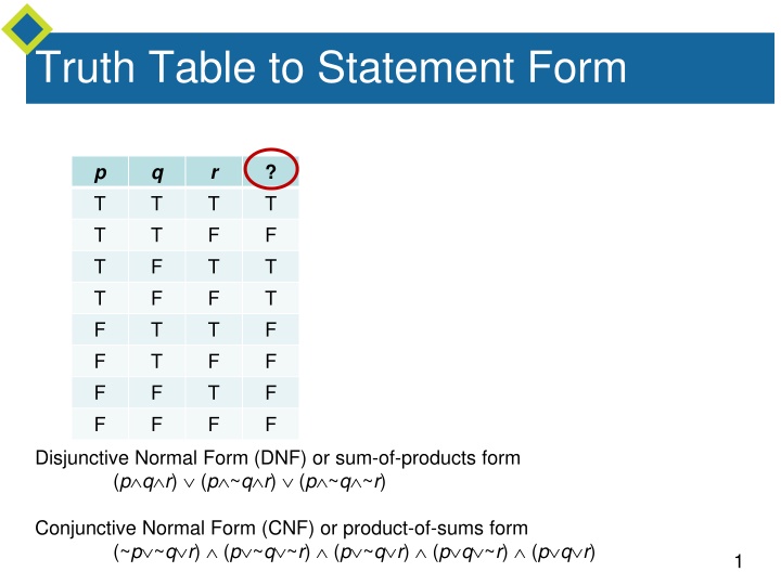
Truth Table to Statement Form p T T T T F F F F q T T F F T T F F r T F T F T F T F ? T F T T F F F F Disjunctive Normal Form (DNF) or sum-of-products form (p q r) (p ~q r) (p ~q ~r) Conjunctive Normal Form (CNF) or product-of-sums form (~p ~q r) (p ~q ~r) (p ~q r) (p q ~r) (p q r) 1
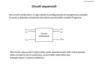
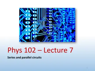
Application: Digital Logic Circuits More complicated circuits correspond to more complicated logical expressions. Electrical engineers continue to use the language of logic when they refer to values of signals produced by an electronic switch as being true (1) or false (0). The symbols 0 and 1 are called bits, short for binary digits. 2
Gates An efficient method for designing more complicated circuits is to build them by connecting less complicated black box circuits. Three such circuits are NOT-, AND-, and OR-gates. 3
Circuits v.s. Logic Input signals: P = 0 and Q = 1 R ~P Q 4
Circuits v.s. Logic A dot indicates a soldering of two wires. Wires that cross without a dot are assumed not to touch. P Q (P Q) ~ (P Q) ~ (P Q) P Q 5
The Boolean Expression Corresponding to a Circuit In logic, variables such as p, q and r represent statements, and a statement can have one of only two truth values: T(true) or F(false). A statement form is an expression, such as p ( q r), composed of statement variables and logical connectives. Any variable, such as a statement variable or an input signal, that can take one of only two values is called a Boolean variable. An expression composed of Boolean variables and the connectives , , and is called a Boolean expression. 6
Black Boxes and Gates Focuses attention on the relation between the input and the output signals. The operation is completely specified by constructing an input/output table that lists all possible input signals together with their corresponding output signals. 7
Black Boxes p T T T T F F F F q T T F F T T F F r T F T F T F T F ? T F T T F F F F S (P Q R) (P ~Q R) (P ~Q ~R) S (~P ~Q R) (P ~Q ~R) (P ~Q R) (P Q ~R) (P Q R) 8
Example 5 Solution cont d Then draw the diagram for (P Q R) (P ~Q R) (P ~Q ~R) 9
Simplifying Combinational Circuits Consider the two combinational circuits shown below. (a) (b) 10
NAND and NOR Gates Another way to simplify a circuit is to find an equivalent circuit that uses the fewest different kinds of logic gates. Two gates not previously introduced are particularly useful for this: NAND-gates and NOR-gates. NAND-gate: acts like an AND-gate followed by a NOT- gate; represented by a Sheffer stroke | . NOR-gate: acts like an OR-gate followed by a NOT-gate; represented by a Peirce arrow . 12
NAND and NOR Gates It can be shown that any Boolean expression is equivalent to one written entirely with Sheffer strokes or entirely with Peirce arrows. Thus any digital logic circuit is equivalent to one that uses only NAND-gates or only NOR-gates. 14
Example 7 Rewriting Expressions Using the Sheffer Stroke Use logical equivalences to show that 15
Example 7 Rewriting Expressions Using the Sheffer Stroke Use logical equivalences to show that Use logical equivalences to show that P Q (P|Q)|(P|Q) NAND ( | ) is functionally complete. 16
Summary of Logical Equivalences A number of logical equivalences are summarized in Theorem 2.1.1 for future reference. 17
Summary of Rules of Inference Table 2.3.1 summarizes some of the most important rules of inference. Valid Argument Forms Table 2.3.1 18