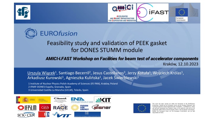
Feasibility Study and Validation of PEEK Gasket for DONES STUMM Module
This work presents a feasibility study and validation of a PEEK gasket for the DONES STUMM module at the AMICI-I FAST Workshop in Krakow. The collaborative effort, led by researchers from various institutions, investigates the potential application of the gasket in accelerator components. The study is part of the EUROfusion Consortium and aims to advance fusion materials research. Images showcase the IFMIF-DONES Laboratory and the International Fusion Materials Irradiation Facility, highlighting key personnel and facilities involved in this innovative project.
Download Presentation

Please find below an Image/Link to download the presentation.
The content on the website is provided AS IS for your information and personal use only. It may not be sold, licensed, or shared on other websites without obtaining consent from the author.If you encounter any issues during the download, it is possible that the publisher has removed the file from their server.
You are allowed to download the files provided on this website for personal or commercial use, subject to the condition that they are used lawfully. All files are the property of their respective owners.
The content on the website is provided AS IS for your information and personal use only. It may not be sold, licensed, or shared on other websites without obtaining consent from the author.
E N D
Presentation Transcript
Feasibility study and validation of PEEK gasket for DONES STUMM module AMICI-I.FAST Workshop on Facilities for beam test of accelerator components Krak w, 12.10.2023 Urszula Wi cek1, Santiago Becerril2, Jesus Castellanos3, Jerzy Kotu a1, Wojciech Kr las1, Arkadiusz Kurowski1, Agnieszka Kuli ska1, Jacek wierblewski1 1 Institute of Nuclear Physics Polish Academy of Sciences (IFJ PAN), Krak w, Poland 2 IFMIF-DONES Espa a, Granada, Spain 3 Universidad Castilla La Mancha (UCLM), Toledo, Spain This work has been carried out within the framework of the EUROfusion Consortium, funded by the European Union via the Euratom Research and Training Programme (Grant Agreement No 101052200 EUROfusion). Views and opinions expressed are however those of the author(s) only and do not necessarily reflect those of the European Union or the European Commission. Neither the European Union nor the European Commission can be held February 2005 responsible for them.
IFMIF IFMIF- -DONES DONES Laboratory Laboratory IFMIF IFMIF- -DONES DONES- - International Fusion Materials Irradiation Facility International Fusion Materials Irradiation Facility DEMO DEMO Oriented OrientedNeutron Source Neutron Source EUROfusion EUROfusionConsortium ( (Work WorkPackage ConsortiumWPENS Project WPENS Project PackageEarly EarlyNeutron Source) Neutron Source) Division of Scientific Equipment and Infrastructure Construction (DAI) Department of Radiation Transport Physics (NZ61) Jan Dankowski Barbara Gaba ska Andrzej Igielski Wojciech Kr las Agnieszka Kuli ska Arkadiusz Kurowski Urszula Wi cek Dariusz Bocian Marcin Cury o Jerzy Kotu a Rafa Ortwein Przemys aw W chal Jacek wierblewski Wojciech Marek 2
IFMIF IFMIF- -DONES DONES Laboratory Laboratory IFMIF IFMIF- -DONES DONES- - International Fusion Materials Irradiation Facility International Fusion Materials Irradiation Facility DEMO DEMO Oriented OrientedNeutron Source Neutron Source EUROfusion EUROfusionConsortium ( (Work WorkPackage ConsortiumWPENS Project WPENS Project PackageEarly EarlyNeutron Source) Neutron Source) Esc zar site (ca. 10 ha), 18 km southwest from Granada, Spain 3
IFMIF IFMIF- -DONES DONES Laboratory Laboratory IFMIF IFMIF- -DONES DONES- - International Fusion Materials Irradiation Facility International Fusion Materials Irradiation Facility DEMO DEMO Oriented OrientedNeutron Source Neutron Source EUROfusion EUROfusionConsortium ( (Work WorkPackage ConsortiumWPENS Project WPENS Project PackageEarly EarlyNeutron Source) Neutron Source) Esc zar site (ca. 10 ha), 18 km southwestfrom Granada, Spain 4
IFMIF IFMIF- -DONES DONES Laboratory Laboratory STUMM Start Up Monitoring Module A. Ibarra et al., Nuclear Fusion 58, 105002 (2018) W. Kr las et al., Nuclear Fusion 61, 125002 (2021) Test Cell (TC) - the space dedicated to irradiations. HFTM High Flux Test Module F. Arbeiter et al., Nuclear Materials and Energy (2016) 5
STUMM STUMM Start Start Up Up Monitoring Module Monitoring Module Rabbit System Container Reaction Threshold [MeV] In-115 (n,n ) In-115m 0.4 Ni-58 (n,p) Co-58 1.0 Ti-47 (n,p) Sc-47 1.5 Ti-46 (n,p) Sc-46 3.5 Ti-48 (n,p) Sc-48 7.0 Active part of rig Nb-93 (n,2n) Nb-92m 8.9 Ni-58 (n,2n) Ni-57 12.4 Detection Detectionsystems systems for STUMM: for STUMM: Cu-63 (n,3n) Cu-61 20.0 Y-89 (n,3n) Y-87m 21.5 Rabbit system (RS) Rabbit system (RS) (x8) (1 per rig) thermal, epithermal and fast neutrons MFC (U238) & IC MFC (U238) & IC (max 140) - fast neutrons MFC (U235) MFC (U235) or or SPND detectors SPND detectors (max 40) thermal and epithermal neutrons Gamma thermometers Gamma thermometers (max 40) nuclear heating Thermocouples Thermocouples ( max 40) temperature Bi-209 (n,4n) Bi-206 22.6 Single Rig Tm-169 (n,4n) Tm-166 23.7 6
STUMM STUMM Start Start Up Up Monitoring Module Monitoring Module Rabbit system Initial Conditions Gas pressure in Test Cell 0.2 bar Gas pressure in STUMM (Helium gas) 3 3.5 bar Rigs Maximum drop pressure in STUMM 0.6 0.8 kPa Electrical conectors The maximum mass flow rate of the cooling medium 0.18 kg/s max to 60 C Cooling gas temperature at the inlet 150 C STUMM Ver. 2022 Maximum temperature of the cooling gas at the outlet 200 C - 250 C Maximum temperature inside Container Heat generation from MCNP calculations up to 1014 - 1015n/cm2/s Neutron flux density Gamma-ray dose ~GGy per year Heat exchange (radiation, conduction in He-gas) with the Target Assembly at 300 C The tolerated leakage for each flange shall be equal to 2 10-4Pa m3/s based on a total tolerated leakage from HFTM to TC of 10-2Pa m3/s 7
STUMM STUMM Start Start Up Up Monitoring Module Monitoring Module Rabbit system Requirements: Rigs STUMM shall be able work in more than one irradiation cycle - replaceable rigs Electrical conectors STUMM shall be a system tightness STUMM Ver. 2022 General issues: It is very difficult to ensure both Each rig must be sealed. Large amount of detectors in the current design (240). 2 or 3 multi-pin (20 pins) connectors per rig for the most instrumented rigs. Limited space for access via RH. 8
PEEK as a PEEK as a gasket gasket for STUMM for STUMM Rabbit system The general assumptions: Rigs Propose material for the rigs gasket PEEK (Polyether ether ketone) Electrical conectors One gasket for all rigs STUMM Ver. 2022 9
PEEK as a PEEK as a gasket gasket for STUMM for STUMM Radiation resistance of PEEK: Based on ITER Report (RHYTUK): Radiation damage properties of Polyether ether ketone (PEEK) Good radiation resistance and keep its mechanical properties up to 10 20 MGy Is recommended to use for the radiation dose up to 1.5 MGy Most of the presented tests for gamma ray (or electron beam) For combined radiation fields (neutrons and gamma) PEEK degrades faster MGy/fpy The parameters of PEEK are improved while the dose is increased There is a risk that the PEEK seal will lose its properties and will not be reusable. The absorbed dose (MGy/fpy) of PEEK (Rep EFDA 2NF525 v.1.4). At the upper part of HFTM/STUMM is foreseen above 50 MGy / fpy. 10
PEEK as a PEEK as a gasket gasket for STUMM for STUMM The general questions are: Is this solution feasible? Is it possible to reuse the same gasket (PEEK) after rig replacemant? Experimental validation of the PEEK gasket reusing A simple system consisting of following elements: The vacuum chamber PEEK o-ring seals He leak detector A set of pipes The vacuum pumping station 11
Experimental Experimental validation validation of the PEEK of the PEEK gasket gasket reusing reusing Results of the tightness test of the seal made of PEEK Mechanical test Positive Negative Radiation hardness test Revision of the design & requiremants Other materials for rig gasket Positive OK! Negative 12
Experimental Experimental validation validation of the PEEK of the PEEK gasket gasket reusing reusing Pressure control Set-up for test experiments: High vacuum chamber (Pressure during typical experiments up to ~3x10⁻⁶mbar) The front flange DN 210 ISO-K (uses clamp fasteners) The rear flange DN 210 ISO-F (uses bolt fasteners). Pumping system the set of the rotary and turbo pump Pressure measurement - IONIVAC gauge (Cold Cathode/Pirani Combination Gauge) can measure ~10-10 mbar Pressure control - COMBIVAC gauge controller PEEK gaskets Pressure measurement DN 210 ISO-F High vacuum chamber DN 210 ISO-K Air Valves Pumping system 13
Experimental Experimental validation validation of the PEEK of the PEEK gasket gasket reusing reusing PEEK gaskets Pressure control Pressure measurement DN 210 ISO-F High vacuum chamber DN 210 ISO-K Air Valves PEEK gasket dimensions: A (mm) B (mm) 210 223 210 223 210 238 210 238 Pumping system C (mm) 3 4 3 4 D (mm) 6.5 6.5 14 14 I II III IV 14
Experimental Experimental validation validation of the PEEK of the PEEK gasket gasket reusing reusing Pressure control (GRAPHIX) PEEK gasket dimensions: A (mm) B (mm) 210 223 210 223 210 238 210 238 High vaccum chamber C (mm) 3 4 3 4 D (mm) 6.5 6.5 14 14 I II III IV Main experimental steps: 1. PEEK gasket placed under the front flanche of the HV chamber. 2. Closing and evacuating the HV chamber (~10-4mbar). 3. Pressure control continously ~24 hours. 4. Opening of the chamber, visual check of the PEEK gasket, thickness control. 5. PEEK gasket placed again under the front flanche. Pumping system Set-up for test experiments Steps repeated five times. 15
Experimental Experimental validation validation of the PEEK of the PEEK gasket gasket reusing reusing Preliminary experimental results 16
Experimental Experimental validation validation of the PEEK of the PEEK gasket gasket reusing reusing Results of the tightness test of the seal made of PEEK Mechanical test Positive Negative Radiation hardness test Revision of the design & requiremants Other materials for rig gasket Positive OK! Negative 17
Summary Summary The first results look promising! The next step will be a test of the PEEK gasket after irradiation But the question is: Where this gasket can be irriadiated? - MARIA Reactor - TR24 at NPI-Rez in Czech Republic - LIPAc 18
References: 1. U. Wi cek, A. Kurowski, J. Kotu a, R. Ortwein. System Design Description Document for the IFMIF-DONES Start-Up Monitoring Module (STUMM); Technical Report - EFDA_D_2MNBDB (2023) 2. U. Wi cek, J. Kotu a, A. Kurowski, R. Ortwein 2022 Update of the STUMM Engineering Design ; Report EFDA_D_2PWFB8 (2023) 3. 3D CAD model of STUMM; EFDA_D_2N5PTM v.2.9 (2023) 4. R. Ortwein, U. Wi cek; Conjugated heat transfer analysis of the Start-Up Monitoring Module (STUMM) for IFMIM-DONES including heat generation mapping ; Fusion Eng. Des. 188 (2023) 113451; DOI: https://doi.org/10.1016/j.fusengdes.2023.113451 5. C. Torregrosa-Martin and all, Overview of IFMIF-DONES diagnostics: Requirements and techniques; Fusion Eng. Des 191 (2023) 113556 6. U. Wi cek, and all, New approach to the conceptual design of STUMM: a module dedicated to the monitoring of neutron and gamma radiation fields generated in IFMIF-DONES, Fusion Eng. and Design 172, 112866 (2021). 7. W. Kr las, A. Ibarra and all, The IFMIF-DONES fusion oriented neutron source: evolution of the design, Nucl. Fusion 61, 125002 (2021). 8. R. Ortwein, J. Kotu a, U. Wi cek, J. wierblewski, D. Bocian, Hydraulic analysis of the start-up monitoring module (STUMM) for IFMIF-DONES, Fusion Eng. Des., 171 (2021) 112601, doi: 10.1016/j.fusengdes.2021.112601, 19
IFMIF-DONES principal system 70% Availability 30 years Operation Access Cell TIR Test Cell (Target + Test Systems) Lithium Systems System engineering approach Poster D. S nchez-Herranz, TUPM019 A. Ibarra et al., Nuclear Fusion 58, 105002 (2018) W. Kr las et al., Nuclear Fusion 61, 125002 (2021)
DONES Programme Schedule +1-2 years of irradiation and +1-2 years of PIE First materials data around T0+(13-15)y Some acceleration could be possible, but not very relevant
