Fiber Optic Cables and Installation Basics
Dive into the world of fiber optic cables with this comprehensive guide on structured cabling and installation. Learn about fiber optic terms, basic elements, and how light pulses are used for information transmission. Get insights on core, cladding, coating, attenuation, bandwidth, and more. Enhance your knowledge of fiber optic technology for high-speed networks and long-distance communication.

Download Presentation

Please find below an Image/Link to download the presentation.
The content on the website is provided AS IS for your information and personal use only. It may not be sold, licensed, or shared on other websites without obtaining consent from the author. If you encounter any issues during the download, it is possible that the publisher has removed the file from their server.
You are allowed to download the files provided on this website for personal or commercial use, subject to the condition that they are used lawfully. All files are the property of their respective owners.
The content on the website is provided AS IS for your information and personal use only. It may not be sold, licensed, or shared on other websites without obtaining consent from the author.
E N D
Presentation Transcript
Structured cabling and Installation Lecture Two By: Eyob Gebretinsae AAiT, Centre of Information Technology and Scientific Computing 2012 E.C
Data Cables Contents Fiber Cables Multi-Mode Cable Single Mode Cable AAiT, Centre of Information Technology and Scientific Computing 2012 E.C
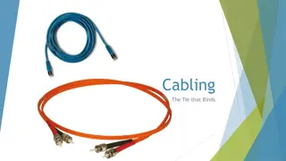
Fiber Cable Fiber optic cables consist of a glass core and cladding, buffer coating, Kevlar strength members and a protective outer jacket. Fiber optic cables use light pulses as opposed to electrical signals to send information. Light passes through the cable, bouncing off the cladding until it reaches the other end of the fiber channel - this is called total internal reflection. In today s high speed networks fiber cable is used to improve light transmission over long distances. AAiT, Centre of Information Technology and Scientific Computing 2012 E.C
Basic Elements The three basic elements of a fiber optic cable are the core, the cladding and the coating. AAiT, Centre of Information Technology and Scientific Computing 2012 E.C
Core: This is the light transmission area of the fiber, either glass or plastic. The larger the core, the more light that will be transmitted into the fiber. Cladding: The function of the cladding is to provide a lower refractive index at the core interface in order to cause reflection within the core so that light waves are transmitted through the fiber. Coating: Coatings are usually multi-layers of plastics applied to preserve fiber strength, absorb shock and provide extra fiber protection. These buffer coatings are available from 250 microns to 900 microns. AAiT, Centre of Information Technology and Scientific Computing 2012 E.C
Fiber Optic Terms Absorption: One cause of attenuation where light signal is absorbed into the glass during transmission. Attenuation: Optical loss of power. Attenuation is measured in dB loss per length of cable. Attenuation is usually caused by absorption and scattering. Attenuator: A device used to reduce the power of an optical signal. Back Reflection: A measure of the light reflected off the polished end of a fiber connector. Measured in negative dB relative to incident power. AAiT, Centre of Information Technology and Scientific Computing 2012 E.C
Bandwidth: The range of signal frequencies that a fiber optic cable will transmit. Buffer: The protective coating over the fiber. Insertion Loss: The attenuation caused by the insertion of a device (such as a splice or connection point) to a cable. Loss Budget: The maximum amount of power that is allowed to be lost per optical link. AAiT, Centre of Information Technology and Scientific Computing 2012 E.C
Return Loss: The ratio of the power launched into a cable and the power of the light returned down the fiber. This measurement is expressed in positive decibel units (dB). A higher number is better. Return Loss = 10 log (incident power / returned power). Scattering: A second cause of attenuation. Scattering occurs when light collides with individual atoms in the glass. Wavelength: A means of measuring light color. Expressed in nanometers (nm). AAiT, Centre of Information Technology and Scientific Computing 2012 E.C
Fiber Size The size of a fiber is measured using micron ( m) A micron ( m) is equal to one millionth of a meter. E.g. A sheet of paper is approximately 25 microns thick. 25 microns are equal to 0.0025 cm. The size of the optical fiber is commonly referred to by the outer diameter of its core, cladding and coating. Example: 50/125/250 indicates a fiber with a core of 50 microns, cladding of 125 microns, and a coating of 250 microns. AAiT, Centre of Information Technology and Scientific Computing 2012 E.C
Fiber Cable types Fiber can be identified by the type of paths that the light rays, or modes, travel within the fiber core. There are two basic types of fiber: multimode and single-mode. Single-mode fiber cables have extremely small core diameters, ranging from 5 to 9.5 um. The core is surrounded by a standard cladding diameter of 125 um. AAiT, Centre of Information Technology and Scientific Computing 2012 E.C
The single mode fiber allows only a single light ray or mode to be transmitted down the core Single-mode fibers have the potential to carry signals for long distances with low loss, and are mainly used in communication systems. AAiT, Centre of Information Technology and Scientific Computing 2012 E.C
Multimode Fiber Multimode fiber cables have bigger diameters that their single- mode counterparts Multimode fiber cores may be either step index or graded index. Step index multimode fiber is sharp step like difference in the refractive index of the core and cladding. In the more common graded index multimode fiber the light rays are also guided down the fiber in multiple pathways. AAiT, Centre of Information Technology and Scientific Computing 2012 E.C
But unlike step index fiber, a graded index core contains many layers of glass, each with a lower index of refraction as you go outward from the axis. AAiT, Centre of Information Technology and Scientific Computing 2012 E.C
OM1, OM2, OM3, OM4 fiber optic cable Multimode fiber cable is prefixed with 'OM' and In ISO/IEC 11801 and EIA/TIA standards four types of Multimode OM1, OM2, OM3 & OM4 are mentioned. The main difference between OM and OS type cables is in core diameter with OM multimode fibers has a much larger core size. Two types of OM cables with core diameters of 50 micron and 62.5 micron are specified. AAiT, Centre of Information Technology and Scientific Computing 2012 E.C
Conventional 62.5/125 m (OM1) and 50/125 m (OM2) multi- mode cables were widely deployed in premises applications for many years. AAiT, Centre of Information Technology and Scientific Computing 2012 E.C
OS1, OS2 fiber optic cable Single mode fiber cable is prefixed with 'OS'. In ISO/IEC 11801 and EIA/TIA standards two types of Single mode OS1 & OS2 fibers are mentioned. The difference between OS1 and OS2 fiber optic cables is mainly in cable construction rather than optical fiber specifications. OS1 type cable is predominantly of a tight buffered construction whereas OS2 is a loose tube or blown cable construction where the cable designs applies less stress on the optical fibers. AAiT, Centre of Information Technology and Scientific Computing 2012 E.C
OS1 fiber optic cable is designed for premises where the maximum distance is 2,000 meters with transmission speeds of 1 to 10 gigabit Ethernet. OS2 fiber optic cable is designed for larger transmission distances in the range of 5,000 to 10,000 meters with similar transmission speed of 1 to 10 gigabit Ethernet. AAiT, Centre of Information Technology and Scientific Computing 2012 E.C


 and 50/125 µm (OM2)")