Five-Stage Processor Overview in Computer Science 3220 - Fall 2014
Explore a detailed tour of a five-stage processor in Computer Science 3220, Fall 2014, covering stages, signal naming, stage functionalities, datapath flow, control flow issues, and interrupt-related aspects. Gain insights into the classical 5-stage pipeline, signal handling, datapath operations, and more.

Download Presentation

Please find below an Image/Link to download the presentation.
The content on the website is provided AS IS for your information and personal use only. It may not be sold, licensed, or shared on other websites without obtaining consent from the author. If you encounter any issues during the download, it is possible that the publisher has removed the file from their server.
You are allowed to download the files provided on this website for personal or commercial use, subject to the condition that they are used lawfully. All files are the property of their respective owners.
The content on the website is provided AS IS for your information and personal use only. It may not be sold, licensed, or shared on other websites without obtaining consent from the author.
E N D
Presentation Transcript
A Tour of A Five-Stage Processor CS 3220 Fall 2014 A C Hadi Esmaeilzadeh hadi@cc.gatech.edu Georgia Institute of Technology T Some slides adopted from Prof. Milos Prvulovic Alternative,Computing,Technologies
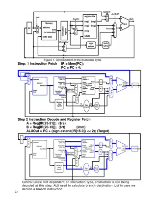
The Stages Classical 5-stage pipeline (like in CS 2200) Fetch Decode ALU Memory Write Register Signal Naming Issues Many signals go through multiple stages Need to give them separate names We ll use sig_F, sig_D, sig_A, sig_M E.g. wregno_M is wregno in the M(EM) stage 3 Apr 2014 Processor Tour 2
What Each Stage Does Obvious stuff what the name of the stage says Additional stuff Fetch also do PC prediction Decode also read register, start pcgood computation ALU also do most of the pcgood computation Possible to complete pcgood here but makes cycle longer MEM lots of additional stuff here Read/Write memory-mapped device registers Generate pcgood and mispred signals Take interrupt if needed, update system registers if int or RETI Read/write system registers for RSR/WSR Write Reg also update bpred table 3 Apr 2014 Processor Tour 3
Tour Itinerary First we ll look at what happens in the datapath Things that determine memory and register values Also includes forwarding and stall signals Then we ll look at control flow issues Things that determine what gets fetched Finally, we ll look at interrupt-related stuff Including how to check and update S* registers 3 Apr 2014 Processor Tour 4
The Datapath - Fetch Almost trivial PC to imem, get inst_F 3 Apr 2014 Processor Tour 5
The Datapath FtoD Flip-Flops Trivial, except if flush or stall reg [(DBITS-1):0] inst_D; reg flushed_D; always @(posedge clk) if(lock) begin if(flush_F) {inst_D,flushed_D}<={32 hXXXXXXXX,1 b1}; else if(!stall_D) {inst_D,flushed_D}<={inst_F,1'b0}; end What is the purpose of flushed_D signal? Indicates to later stage if this is a real inst or a bubble Why? Because it may come handy 3 Apr 2014 Processor Tour 6
The Datapath Decode Take inst_D, generate all sorts of signals Give nice names to parts of inst_D first wire [3:0] op1_D =inst_D[31:28]; wire [3:0] rd_D =inst_D[27:24]; wire [3:0] rs_D =inst_D[23:20]; wire [3:0] rt_D =inst_D[19:16]; wire [3:0] op2_i_D =inst_D[ 3: 0]; wire [3:0] op2_d_D =rd_D; wire [3:0] op2_t_D =rt_D; wire [(IMMBITS-1):0] rawimm_D=inst_D[(IMMBITS-1):0]; This is not really needed Could use inst_D[31:28] instead of op1_D But op1_D is more descriptive 3 Apr 2014 Processor Tour 7
The Datapath Decode Generate (almost) all control signals Not just those we need in the D stage case(op1_D) OP1_ALUR: begin {rdreg1_D,rdreg2_D,aluimm_D,wrreg_D} { 1'b1, 1'b1, 1'b0, 1'b1}; case(op2_i_D) OP2_ALU_ADD: {selarith_D,arithsub_D}= { 1'b1, 1'b0}; ... ALU_OP2_NXOR: {sellogic_D,logicop_D,logicneg_D}= { 1'b1,LOGIC_XOR, 1'b1}; default: iinst_D=1'b1; endcase 3 Apr 2014 Processor Tour 8
The Datapath Decode And read registers, of course wire [2:0] rregno1_D=rs_D, rregno2_D=rt_D; wire [(DBITS-1):0] regout1_D,regout2_D; RegFile #(.DBITS(DBITS),.ABITS(REGNOBITS),.MFILE("Regs.mif")) regFile(.RADDR1(rregno1_D),.DOUT1(regout1_D), .RADDR2(rregno2_D),.DOUT2(regout2_D), .WADDR(wregno_W), .DIN(result_W), .WE(wrreg_W),.CLK(clk)); 3 Apr 2014 Processor Tour 9
The Datapath Decode Do forwarding and generate stall signals! wire forw1A_D=wrreg_A&&(rregno1_D==wregno_A); wire forw2A_D=wrreg_A&&(rregno2_D==wregno_A); wire stallA_D=((forw1A_D&&rdreg1_D)||(forw2A_D&&rdreg2_D))&& (!gotresult_A); wire forw1M_D=wrreg_M&&(rregno1_D==wregno_M); wire forw2M_D=wrreg_M&&(rregno2_D==wregno_M); wire forw1W_D=wrreg_W&&(rregno1_D==wregno_W); wire forw2W_D=wrreg_W&&(rregno2_D==wregno_W); wire [(DBITS-1):0] regval1_D=forw1A_D?result_A: forw1M_D?result_M: forw1W_D?result_W: regout1_D; wire [(DBITS-1):0] regval2_D=forw2A_D?result_A: forw2M_D?result_M: forw2W_D?result_W: regout2_D; wire stall_D=stallA_D; wire stall_F=stall_D; 3 Apr 2014 Processor Tour 10
The Datapath D2A Flip-Flops Lots of signals (from decoding)! always @(posedge clk) begin {regval1_A,regval2_A,imm_A,aluimm_A}<= {regval1_D,regval2_D,imm_D,aluimm_D}; {logicop_A,logicneg_A,arithsub_A,complt_A,compeq_A}<= {logicop_D,logicneg_D,arithsub_D,complt_D,compeq_D}; {selpcplus_A,sellogic_A,selarith_A,selcomp_A,selmem_A,selsreg_A}<= {selpcplus_D,sellogic_D,selarith_D,selcomp_D,selmem_D,selsreg_D}; {wrmem_A,rregno1_A,wsreg_A,reti_A,wrreg_A,wregno_A}<= {wrmem_D,rregno1_D,wsreg_D,reti_D,wrreg_D,wregno_D}; {iinst_A,sinst_A,flushed_A}<= {iinst_D,sinst_D,flushed_D}; if(flush_D||stall_D) {wrmem_A,wsreg_A,reti_A,wrreg_A,iinst_A,sinst_A,flushed_A}<= {1'b0 ,1'b0 ,1'b0 ,1'b0 , 1'b0, 1'b0, 1'b1}; end 3 Apr 2014 Processor Tour 11
The Datapath Fast ALU Determine ALU inputs wire [(DBITS-1):0] aluin1=regval1_A; wire [(DBITS-1):0] aluin2=aluimm_A?sxtimm_A:regval2_A; Generate result for each operation wire [(DBITS-1):0] resarith_A= aluin1+(aluin2^{DBITS{arithsub_A}})+arithsub_A; wire rescomp_A=((aluin1<aluin2)&&complt_A)|((aluin1==aluin2)&&compeq_A); wire [(DBITS-1):0] vallogic_A= (logicop_A==LOGIC_AND)?(aluin1&aluin2): (logicop_A==LOGIC_OR )?(aluin1|aluin2): (logicop_A==LOGIC_XOR)?(aluin1^aluin2):{DBITS{1'bX}}; wire [(DBITS-1):0] reslogic_A={DBITS{logicneg_A}}^vallogic_A; Select final ALU result Use sel*_A signals Memory address? It s in resarith_A! 3 Apr 2014 Processor Tour 12
The Datapath A2M Flip-Flops Fewer signals (ALU control not needed here) No stalls here Stalls are needed to delay instruction until forwarding can provide correct register values always @(posedge clk) begin {regval1_M,regval2_M,rregno1_M,wsreg_M,reti_M,wregno_M,wrreg_M}<= {regval1_A,regval2_A,rregno1_A,wsreg_A,reti_A,wregno_A,wrreg_A}; {dmemaddr_M,wrmem_M,restmp_M,gotrestmp_M}<= {dmemaddr_A,wrmem_A,result_A,gotresult_A}; {selmem_M,selsreg_M}<={selmem_A,selsreg_A}; {iinst_M,sinst_M,flushed_M}<= {iinst_A,sinst_A,flushed_A}; if(flush_A) begin {wrmem_M,wsreg_M,reti_M,wrreg_M,iinst_M,sinst_M,flushed_M}<= {1'b0 ,1'b0 , 1'b0, 1'b0, 1'b0, 1'b0, 1'b1}; end end 3 Apr 2014 Processor Tour 13
The Datapath Memory Feed dmemaddr_M and wrmem_M to memory and I/O devices They read/write the actual memory and I/O registers Reads put values on dbus, which feeds result_M 3 Apr 2014 Processor Tour 14
The Datapath M2W FFs and W Stage Very simple FFs no stalls, no flushes If an inst got to M stage, it is safe reg wrreg_W=1 b0; reg [(REGNOBITS-1):0] wregno_W; reg [(DBITS-1):0] result_W; always @(posedge clk) if(!init) begin {wrreg_W,wregno_W,result_W}<= {wrreg_M,wregno_M,result_M}; end No real code for the W stage Just feed wrreg_W, wregno_W, and result_M signals to the register file 3 Apr 2014 Processor Tour 15
Control Flow Fetch Update PC every cycle wire [(DBITS-1):0] PCpred_F; always @(posedge clk) if(lock) begin if(init) PC<=32'h40; else if(mispred_M) PC<=pcgood_M; else if(!stall_F) PC<=pcpred_F; // From bptable End wire [(DBITS-1):0] pcplus_F=PC+32'd4; Compute pcplus (PC+4) Branch predictor We ve already seen the code for this 3 Apr 2014 Processor Tour 16
Control Flow FtoD Flip-Flops Carry PC, PCplus, PCpred to next stage always @(posedge clk) if(lock) begin if(flush_F) always @(posedge clk) begin if(flush_F) {PC_D ,pcplus_D,pcpred_D}<= {32'b0,pcgood_B,pcgood_B}; else if(!stall_D) {PC_D,pcplus_D,pcpred_D}<= {PC ,pcplus_F,pcpred_F}; end {inst_D,flushed_D}<=... else if(!stall_D) {inst_D,flushed_D}<=... end Note how flush and stall mirrors datapath FtoD It s really one big FtoD set of FFs! We just separate them in our code for clarity 3 Apr 2014 Processor Tour 17
Control Flow Decode Compute btarg, jtarg is just regval1_D) wire [(DBITS-1):0] brimm_D= {{(DBITS-IMMBITS-1){imm_D[IMMBITS-1]}},imm_D,1'b0}; wire [(DBITS-1):0] btarg_D=pcplus_D+brimm_D; wire [(DBITS-1):0] jtarg_D=regval1_D+brimm_D; What else do we need to compute pcgood? Why not compute pcgood here? 3 Apr 2014 Processor Tour 18
Control Flow ALU The pcgood saga continues! Find how regval1_A and regval2_A compare Now that we have these values! Use this and isbranch_A to determine dobranch_A Now we can determine pcgood! But do we want to? And then find mispred as (pcgood!=pcpred) And then feed it to the PC-selection logic in F stage 3 Apr 2014 Processor Tour 19
Control Flow - Memory Take btarg_M, jtarg_M, dobranch_M, etc. and finally detemine pcgood Also compute mispred_M Can compute it as (pcgood_M!=pcpred_M) Takes some time AFTER the pcgood is computed And then we need to get mispred_M across wires to PC selection There is a MUCH better way to generate mispred_M Think: Can I do some comparisons in earlier stages so that I can determine mispred_M quickly in the M stage This would give mispred_M more time to get to the F stage 3 Apr 2014 Processor Tour 20
The Much Better Way 3 Apr 2014 Processor Tour 21
Control Flow Write Reg Stage But we already did pcgood and mispred stuff! What is left to do? Update the branch predictor table! reg [(DBITS-1):0] PC_W,pcgood_W; always @(posedge clk) begin {PC_W,pcgood_W}<= {PC_M,pcgood_M}; end wire [(BPABITS-1):0] bpUpdInd=PC_W[BPABITS:1]; always @(posedge clk) if(PC_W!=16'b0) begin bptable[bpUpdInd]<=pcgood_W; end Why don t we have if(init) stuff in this code? 3 Apr 2014 Processor Tour 22
System/Interrupt Support It s all in M stage S* registers read/written in M stage for RSR/WSR Eliminates forwarding of S* register values from WSR to RSR RSR and LW use the same forwarding to other insts So S* reads and writes for int/RETI are also in M stage Eliminates forwarding of S* values between int/RETI and WSR/RSR And int/RETI will keep insts in M stage and flush F,D,A Same flush as for branch misprediction (assuming pcgood done in M) If we had pcgood computation finish in A stage? Then we would have all of this in the A stage Don t want to have two different kinds of flushes! Doable, but we do want to finish Project 5 this semester 3 Apr 2014 Processor Tour 23
The S* registers Declare the registers! reg IE, OIE, CM, OM; reg [(DBITS-1):0] SIH, SRA, IDN; Reading them on RSR? reg [(DBITS-1):0] sregout_M; always @(rregno1_M or IE or OIE or CM or OM or SIH or SRA or ...) case(rregno1_M) SREG_SCS: sregout_M={{(DBITS-4){1'b0}},OM,CM,OIE,IE}; SREG_SIH: sregout_M=SIH; SREG_SRA: sregout_M=SRA; SREG_SII: sregout_M=IDN; default: sregout_M=32'hFAFAFAFA; endcase assign rbus=selsreg_M?sregout_M:{DBITS{1'bz}}; // Can we have this to get ALU result to go to register? assign rbus=(!selmem_M)?restmp_M:{DBITS{1'bz}}; 3 Apr 2014 Processor Tour 24
Updating SCS, SII, etc. Some of these registers are updated by WSR, e.g. WSR PCS, A0 Taking an illegal instruction exception Illegal inst in A stage, if not flushed by what we have in M stage Taking interrupt from I/O devices Interrupt request is active and IE is 1 All three may need to be considered each cycle WSR changes IE from 0 to 1 and CM from 1 to 0 Next instruction is RSR (illegal if CM is 0) There is an interrupt request pending 3 Apr 2014 Processor Tour 25
Example: Updating IE What can change IE? Instruction in M stage changes IE WSR RETI Interrupt taken (change IE to 0) Which value of IE do we use? Lets try the value from the beginning of the cycle 3 Apr 2014 Processor Tour 26
Update in Several Steps Current M-stage inst vs. illegal A-stage inst Current instruction changes what is legal for next inst, so current instruction updates S* first Current M-stage inst vs. interrupt Current instruction may disable interrupts, interrupt should not appear right after it Illegal inst vs. interrupt Each would change IE to 0, if interrupt goes first it gets higher priority than illegal inst OK, so we have to consider current M-stage inst first, then illegal A-stage inst, then interrupts 3 Apr 2014 Processor Tour 27
Effects of the M-Stage Instruction Do what RETI and WSR need to do Produce temporary values (don t write to regs yet!) reg OIEinst_M,IEinst_M; reg [(DBITS-1):0] IHAinst_M, IRAinst_M, IDNinst_M; always @(wsreg_M or wregno_M or regval1_M or creti_M or OM or ...) begin {OIEinst_M,IEinst_M}= {OIE ,IE }; {IHAinst_M,IRAinst_M,IRAinst_M}= {IHA ,IRA ,IRA }; if(creti_M) IEinst_M=OIE; else if(wsreg_M) case(wregno_M) SREG_PCS: {OIEinst_M,IEinst_M}=regval1_M[1:0]; SREG_IHA: IHAinst_M=regval1_M; SREG_IRA: IRAinst_M=regval1_M; ... endcase end 3 Apr 2014 Processor Tour 28
Effects of Device Interrupt Requests Request causes an interrupt But only if IE still 1! And be careful about placing a correct address in SRA reg OIEdev_M,IEdev_M; reg [(DBITS-1):0] IHAdev_M,IRAdev_M,IDNdev_M; reg TakeInt_dev_M; always @(intr_devs or devnum or flushed_M or TakeInt_leg_M or ...) begin {OIEdev_M, IEdev_M }= {OIEinst_M,IEinst_M}; {IHAdev_M, IRAdev_M, IDNdev_M }= {IHAinst_M,IRAinst_M,IDNinst_M}; TakeInt_dev_M=TakeInt_inst_M; if(IEinst_M&&intr_devs&&!flushed_M) begin {OIEdev_M,IEdev_M,IRAdev_M,IDNdev_M}= {IEinst_M,1'b0 ,pcsave_M,devnum }; TakeInt_dev_M=1'b1; end end 3 Apr 2014 Processor Tour 29
What is pcsave_M The next PC as computed by M-stage inst Similar to the pcgood But not quite the same! pcgood is next instruction should be fetched from here pcsave is M-stage inst says we should fetch from here When are these not the same? 3 Apr 2014 Processor Tour 30
Why check for flushed_M Prevents interrupt from being taken if instruction in M stage is a bubble What happens for ints if we don t check? always @(intr_devs or devnum or flushed_M or TakeInt_leg_M or ...) begin ... if(IEinst_M&&intr_devs&&!flushed_M) begin {OIEdev_M,IEdev_M,IRAdev_M,IDNdev_M}= {IEinst_M,1'b0 ,pcsave_M,devnum }; TakeInt_dev_M=1'b1; end end 3 Apr 2014 Processor Tour 31
Now Update S* Registers wire TakeInt_M=TakeInt_dev_M; always @(posedge clk) if(lock) begin if(init) begin {OIE ,IE }<= {1'b0 ,1'b0 }; {IHA ,IRA ,IDN }<= {32'b0 ,32'b0 ,32'b0}; end else begin {OIE ,IE }<= {OIEdev_M,IEdev_M}; {IHA ,IRA ,IDN }<= {IHAdev_M,IRAdev_M,IDNdev_M}; end end Alternative approach Write what happens to OM, what happens to IHA, etc. Must consider all possible combinations of inst, iinst, and intreq 3 Apr 2014 Processor Tour 32
Whats Missing How to compute pcsave and pcgood? Similar to before, just note the difference Which value does RSR read (e.g. for IE)? Value from the beginning of the cycle (IE)? After M-stage inst updates it (IEinst_M)? After update from taking an interrupt (IEnew_M)? 3 Apr 2014 Processor Tour 33