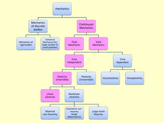
Fluid Mechanics: Properties and Definitions
Explore the fundamental properties of fluids in Fluid Mechanics, including definitions, physical properties like density and viscosity, and their significance in understanding fluid behavior.

Download Presentation

Please find below an Image/Link to download the presentation.
The content on the website is provided AS IS for your information and personal use only. It may not be sold, licensed, or shared on other websites without obtaining consent from the author. If you encounter any issues during the download, it is possible that the publisher has removed the file from their server.
You are allowed to download the files provided on this website for personal or commercial use, subject to the condition that they are used lawfully. All files are the property of their respective owners.
The content on the website is provided AS IS for your information and personal use only. It may not be sold, licensed, or shared on other websites without obtaining consent from the author.
E N D
Presentation Transcript
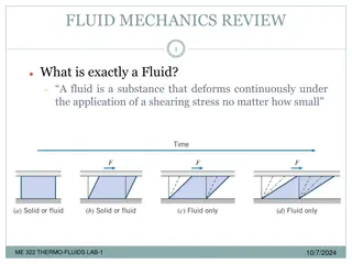
Module 1: Properties of fluids DEFINITION OF A FLUID A substance in the liquid or gas phase is referred to as a fluid. A fluid differs from a solid in that a solid can resist an applied shear stress by deforming by a small amount, whereas a fluid deforms continuously (flows) under the influence of shear stress, no matter how small. The amount of flow that takes place is dependent on various properties of the fluid. www.futuremanagers.com
Module 1: Properties of fluids (continued) PHYSICAL PROPERTIES OF A FLUID: DENSITY The density of a fluid is defined as its mass per unit volume and its units are kg/m3. www.futuremanagers.com
Module 1: Properties of fluids (continued) PHYSICAL PROPERTIES OF A FLUID: SPECIFIC WEIGHT The specific weight of a fluid is defined as its weight per unit volume and its units are N/m3. www.futuremanagers.com
Module 1: Properties of fluids (continued) PHYSICAL PROPERTIES OF A FLUID: COMPRESSIBILITY The compressibility of a fluid is its ability to change its volume under pressure. Compressibility of a liquid is defined as the reciprocal of its bulk modulus (K). Bulk modulus is the ratio between the change in pressure and the volumetric strain and its unit is Pa. www.futuremanagers.com
Module 1: Properties of fluids (continued) PHYSICAL PROPERTIES OF A FLUID: VISCOSITY The viscosity of a fluid is a measurement of the fluid s resistance to flow and its units are Pa.s. It is also referred to as dynamic viscosity or absolute viscosity. www.futuremanagers.com
Module 1: Properties of fluids (continued) PHYSICAL PROPERTIES OF A FLUID: SURFACE TENSION Surface tension is the tension of the surface film of a liquid caused by the attraction of the particles in the surface layer by the bulk of the liquid, which tends to minimise the surface area. This property enables objects with a density higher that water to float on a water surface without becoming even partially submerged. www.futuremanagers.com
Module 2: Pressure systems INTRODUCTION Pressure systems refer to regions within a fluid where the pressure varies. Pressure is defined as the force per unit area and is a crucial concept in understanding the behaviour of fluids. Fluids can include liquids and gases. The study of pressure systems helps explain how fluids move and interact within different environments. www.futuremanagers.com
Module 2: Pressure systems (continued) STATIC PRESSURE Static pressure is the pressure exerted by a fluid at rest and is measured in Pascal. The static pressure in a fluid depends on the height and the specific weight of the fluid. This is the reason why the pressure in a liquid increase with depth and the atmospheric pressure decrease with altitude. www.futuremanagers.com
Module 2: Pressure systems (continued) TYPES OF PRESSURE The different types of pressure are: Atmospheric pressure; Gauge pressure; Absolute pressure; Vapour pressure. www.futuremanagers.com
Module 2: Pressure systems (continued) PRESSURE CALCULATIONS ON MANOMETERS AS PRESSURE MEASURING DEVICES Manometers are used for measuring pressures by balancing the fluid column of the fluid against another column of fluid with known density. Manometers can be classified and further categorised into two types: Simple manometers; and Differential manometers. www.futuremanagers.com
Module 3: Simple hydraulics systems INTRODUCTION A simple hydraulic system refers to a basic mechanism that uses the principles of fluid dynamics to transmit force or energy. Hydraulic systems use a fluid, typically oil or water, to transmit power from one point to another. These systems are widely used in various applications, ranging from heavy machinery and industrial equipment to automotive systems and small tools. www.futuremanagers.com
Module 3: Simple hydraulics systems (continued) ACTUATING CYLINDERS Hydraulic systems like a single hydraulic cylinder, hydraulic jack, hydraulic lift, hydraulic brake system in a vehicle are all examples where Pascal s principle is applied. Actuating means to start or put something into action. www.futuremanagers.com
Module 3: Simple hydraulics systems (continued) HYDRAULIC JACKS The hydraulic jack, hydraulic lift and hydraulic brake system in a car are all examples where the hydraulic system with a mechanical advantage is used. www.futuremanagers.com
Module 3: Simple hydraulics systems (continued) PRESSURE INTENSIFIERS A pressure intensifier boosts hydraulic pressure generating a small quantity of high-pressure fluid from a large quantity of low-pressure fluid. www.futuremanagers.com
Module 3: Simple hydraulics systems (continued) ROTATING SHAFTS AND PISTONS When a shaft is rotating in journal bearings, there will be a viscous resistance acting against the rotation resulting in a loss in torque and power. www.futuremanagers.com
Module 4: Hydrostatic forces on submerged areas INTRODUCTION This can also be referred to as hydrostatic forces on rectangular and circular tanks containing only one type of fluid. www.futuremanagers.com
Module 4: Hydrostatic forces on submerged areas (continued) HYDROSTATIC FORCE ON SIMPLE, FULL RECTANGULAR- AND CYLINDRICAL TANKS POSITIONED VERTICALLY CONTAINING THE SAME FLUID MEDIUM AND CENTRE OF PRESSURE This can also be referred to as hydrostatic forces on rectangular and circular tanks containing two types of fluid. If a tank contains two immiscible fluids, which means that the fluid with the least density will float on top of the denser fluid, the calculations becomes a bit more complicated. www.futuremanagers.com
Module 4: Hydrostatic forces on submerged areas (continued) TOTAL FORCE ON RECTANGULAR AND CYLINDRICAL TANKS POSITIONED VERTICALLY AND CONTAINING ONLY TWO FLUID MEDIUMS AND THEIR CENTRES OF PRESSURE This can also be referred to as hydrostatic forces on plane submerged surfaces. www.futuremanagers.com
Module 5: Buoyancy and stability of floating and immersed bodies INTRODUCTION A solid body dropped into a fluid will sink, float, or remain at rest at any point in the fluid, depending on its density relative to the density of the fluid. Note that when the relative density is equal to or greater than one, the floating body becomes completely submerged. www.futuremanagers.com
Module 5: Buoyancy and stability of floating and immersed bodies (continued) ARCHIMEDES PRINCIPLE The magnitude of the buoyant force acting on an object that is floating or submerged in a fluid can be determined by Archimedes principle which states: When a body is immersed in a fluid either wholly or partially, it is lifted up by a force which is equal to the weight of the fluid displaced by the body and it acts upwards through the centroid of the displaced volume. www.futuremanagers.com
Module 5: Buoyancy and stability of floating and immersed bodies (continued) BUOYANCY The tendency of an immersed body to be lifted up in the fluid due to an upward force opposite to the action of gravity is known as buoyancy. A solid body dropped into a fluid will sink, float, or remain at rest at any point in the fluid. www.futuremanagers.com
Module 5: Buoyancy and stability of floating and immersed bodies (continued) STABILITY Stability refers to the ability of a body in a fluid to return to its original position after being tilted about a horizontal axis. The weight of the body acts vertically downwards through the centre of gravity of the body and the force of buoyancy acts vertically upwards through the centre of gravity of the displaced fluid, which is called the centre of buoyancy. www.futuremanagers.com
Module 5: Buoyancy and stability of floating and immersed bodies (continued) TYPES OF STABILITY Stable: The buoyant force causes a restoring moment which will bring the floating object back to its original position if displaced. Neutral: The centre of gravity and the centre of buoyancy coincide. Unstable: The buoyant force causes an overturning moment which will cause the floating object to topple over. www.futuremanagers.com
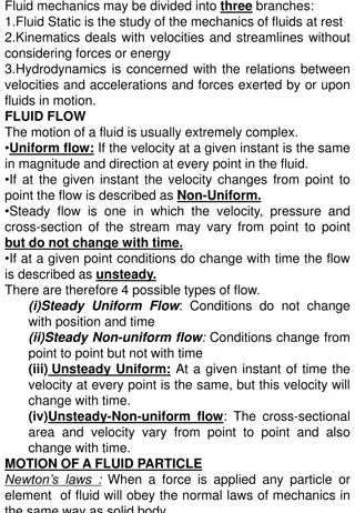
Module 6: Fluid in motion INTRODUCTION Fluid flow is a part of fluid mechanics that deals with the dynamics of fluids. The motion of a fluid subjected to unbalanced forces is known as fluid dynamics. As long as unbalanced pressures are applied, this motion will continue. www.futuremanagers.com
Module 6: Fluid in motion (continued) THE NATURE OF FLUIDS AND TYPES FLOW Flow patterns: A fluid consists of a large number of individual particles moving in the general direction of flow. The velocity of any particle is a vector quantity having magnitude and direction which may vary over time. www.futuremanagers.com
Module 6: Fluid in motion (continued) FLOW TYPES Steady flow; Unsteady flow; Uniform flow; Non-uniform flow; Laminar flow; Turbulent flow. www.futuremanagers.com
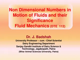
Module 6: Fluid in motion (continued) REYNOLDS NUMBER Reynolds number is a dimensionless quantity that helps predict fluid flow patterns in different situations by measuring the ratio between different forces. www.futuremanagers.com
Module 6: Fluid in motion (continued) FLUID IN MOTION CALCULATIONS Hydrodynamics deals with the flow of water in pipes or open channels. The main difference between pipe flow and open-channel flow is that pipe flow is regarded as fluid that flows in closed conduits and are entirely in contact with rigid boundaries. Open-channel flows, on the other hand, are those whose boundaries are not entirely a solid and rigid material. Due to the differences in those boundaries, different forces affect the two types of flows and different formulae are therefore used in calculations. www.futuremanagers.com
Module 6: Fluid in motion (continued) CONSERVATION OF ENERGY IN FLUIDS The law of conservation of energy states that energy can be neither created nor destroyed, only converted from one kind of energy into another. In other words, the total energy of an isolated system remains constant. The same principle applies to fluid mechanics. www.futuremanagers.com
Module 7: Flow measurement using instruments INTRODUCTION Measuring the flow of liquids is a critical need in many industrial applications. In some operations, the ability to conduct accurate flow measurements is so important that it can make the difference between making a profit or taking a loss. Flow measurement involves using flow meters that measure the amount of fluid moving through a pipe, channel or space by measuring volumetric flow rates. www.futuremanagers.com
Module 7: Flow measurement using instruments (continued) FLOW MEASUREMENT Flow measurement involves using flow meters that measure the amount of fluid moving through a pipe, channel or space by measuring volumetric flow rates. There are many different types of flow meters that can be utilised depending on the nature of the application. www.futuremanagers.com
Module 7: Flow measurement using instruments (continued) FLOW MEASUREMENT: MECHANICAL FLOWMETER Mechanical flow meters consist of a moving part or rotational device. The liquid that passes through the mechanical flowmeter induces rotation or displacement of the moving part. The flow rate that is created in the flowmeter is proportional to the movement of the device. The rotameter is an example of this type of flow meter. www.futuremanagers.com
Module 7: Flow measurement using instruments (continued) FLOW MEASUREMENT: PRESSURE DROP FLOWMETER With most pressure drop-based flow measurement instruments, the flow rate is determined by measuring the fluid s velocity or the change in kinetic energy. Velocity depends on the pressure differential that is forcing the fluid through the pipe. Because the pipe s cross-sectional area is known and remains constant, the average velocity is an indication of the flow rate. The pitot tube and the venturi meter are examples of this type of flow meter. www.futuremanagers.com
Module 7: Flow measurement using instruments (continued) PITOT TUBE Pitot tubes are widely used to determine a boat s water speed, the airspeed of an aircraft, and measure air, liquid and gas flow velocities in various industrial applications. A simple pitot tube consists of a glass tube bent at right angle. The bent part is placed in the centre of the pipe towards the flow of the fluid. www.futuremanagers.com
Module 7: Flow measurement using instruments (continued) VENTURI METER A Venturi meter is a type of differential pressure flow meter that generates flow measurement by measuring the pressure difference at two different locations in a pipe. This pressure difference is created by decreasing the diameter of the pipe, which causes an increase in flow velocity and a corresponding drop in pressure. www.futuremanagers.com
Module 8: Pipeline systems INTRODUCTION In big distribution networks, there are very long lengths of pipes and numerous apparatus in the pipe systems. The losses caused by long lengths of pipes and the existence of fittings, bends and valves in pipelines cannot be ignored when the pressure loss and power needed to drive the fluid need to be calculated. www.futuremanagers.com
Module 8: Pipeline systems (continued) LOSSES IN PIPELINES The kinds of losses that exist in pipelines can be categorised into minor losses (caused by shock) and major losses (due to friction). www.futuremanagers.com
Module 8: Pipeline systems (continued) LOSSES IN PIPELINES: MINOR LOSSES Minor losses are caused by the disruption of flow due to the installation of valves, fittings and bends. These losses do not play a major role in losses that occur in a pipeline, but when each loss is added it can still have a significant influence on the total loss in a pipeline. www.futuremanagers.com
Module 8: Pipeline systems (continued) LOSSES IN PIPELINES: MAJOR LOSSES Major losses are associated with frictional energy loss that is caused by the viscous effects of the fluid and roughness of the pipe wall. Major losses create a pressure drop along the pipe since the pressure must work to overcome the frictional resistance. www.futuremanagers.com
Module 8: Pipeline systems (continued) EQUIVALENT LENGTH Another way to describe the hydraulic resistance of valves and fittings is to use an equivalent-length ratio. This requires converting the shock loss within a fitting, bend or valve to an equivalent length of pipe that would produce the same loss due to its loss coefficient. www.futuremanagers.com
Module 9: Flow through orifices INTRODUCTION An orifice is an opening, of any size or shape, in a pipe or at the bottom or side wall of a container through which fluid is discharged. This opening is typically created by placing a plate or a thin edge within a fluid-carrying pipe or container. The shape and size of the orifice plays a crucial role in determining the characteristics of fluid flow through it. www.futuremanagers.com
Module 9: Flow through orifices (continued) SMALL ORIFICES Orifices may be classified based on their size, shape, sharpness and discharge An orifice is known as a small orifice if the head of liquid from the centre of the orifice is more than five times the depth of the orifice. www.futuremanagers.com
Module 9: Flow through orifices (continued) VENA CONTRACTA Vena contracta is the point in the fluid stream where the cross-sectional area of the stream is the least and fluid velocity is at its maximum. The distance of vena contracta from the orifice is approximately equal to one-half the depth or diameter of the orifice. The stream lines of flow are converging up to the vena contracta and beyond this section the stream lines are parallel. www.futuremanagers.com
Module 9: Flow through orifices (continued) CALCULATIONS FOR ORIFICE FLOW If the geometric properties of the orifice and the properties of the fluid are known, the orifice can be used to measure flow rates and to calculate all the flow coefficients. www.futuremanagers.com
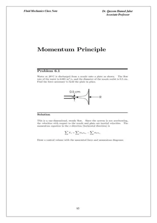
Module 10: Conservation of a momentum (fluid momentum) INTRODUCTION Fluid momentum is a concept in fluid mechanics that describes the motion of a fluid and its resistance to changes in motion. The design of many hydraulic structures, such as tapered pipes and bends, as well as blades in pumps and turbines, depends upon the forces that a fluid flow exerts on them. www.futuremanagers.com
Module 10: Conservation of a momentum (fluid momentum) (continued) FORCE EXERTED BY A JET OF FLUID When a fluid is supplied by a nozzle, a high velocity jet of fluid is produced which is then used to supply water for firefighting equipment or to drive the vanes of pelton wheels or turbines. The momentum equation is used to determine the resultant force exerted by a jet of fluid on vanes as the flow changes its direction or the magnitude of velocity or both. www.futuremanagers.com
Module 10: Conservation of a momentum (fluid momentum) (continued) FORCE ON A STATIONARY PLATE OR VANE When dealing with stationary vanes, only the jet of fluid is moving and the velocity of the vane is zero. The result is that the total mass flow rate of the jet is effective in the dynamic force exerted on the vane. The velocity after it strikes the stationary vane is dissipated and becomes zero. www.futuremanagers.com
Module 10: Conservation of a momentum (fluid momentum) (continued) FORCE ON A MOVING PLATE OR VANE When dealing with a single moving vane, the velocity of the jet relative to the vane will determine the effective mass flow rate impacting on the vane. The length of the jet is continually increasing. Part of the fluid leaving the nozzle is required to extend the length of the jet thus reducing the amount of mass flow that strikes the vane. www.futuremanagers.com
Module 10: Conservation of a momentum (fluid momentum) (continued) FORCE EXERTED ON REDUCERS AND BENDS When dealing with flow in pipelines, two forces need to be considered. The force due to pressure and the dynamic force due to change in momentum have an influence on the total force exerted on reducers and bends in a pipeline. www.futuremanagers.com


")
")
")
")
")

")
")
")

")
")
")
")

")
")


")
")
")
")
")

")
")
")
")
")

")
")
")
")

")
")
")

")
")
")
")