Flux Linkage and Electro-Motive Force in Electric Machines
Explore the concepts of flux linkage and electro-motive force (EMF) in a three-phase winding of rotating electric machines, focusing on the distribution of flux density and coil configurations. Learn how to compute flux per pole and maximum flux linkage for coils, along with details on coil pitch and pitch factors.

Download Presentation

Please find below an Image/Link to download the presentation.
The content on the website is provided AS IS for your information and personal use only. It may not be sold, licensed, or shared on other websites without obtaining consent from the author. If you encounter any issues during the download, it is possible that the publisher has removed the file from their server.
You are allowed to download the files provided on this website for personal or commercial use, subject to the condition that they are used lawfully. All files are the property of their respective owners.
The content on the website is provided AS IS for your information and personal use only. It may not be sold, licensed, or shared on other websites without obtaining consent from the author.
E N D
Presentation Transcript
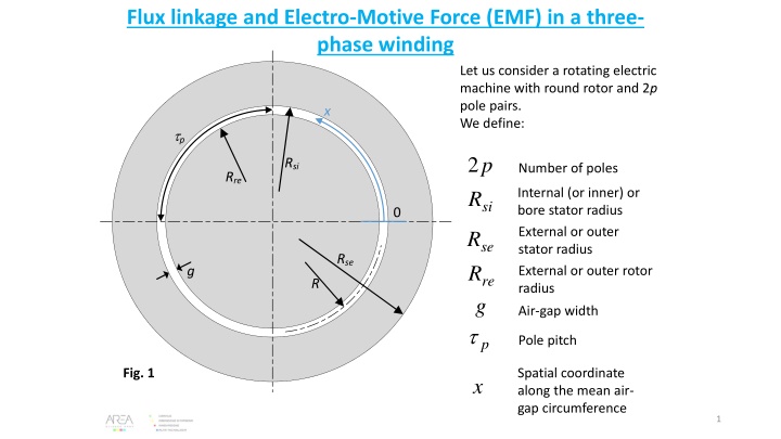
Flux linkage and Electro-Motive Force (EMF) in a three- phase winding Let us consider a rotating electric machine with round rotor and 2p pole pairs. We define: x tp 2 R p Rsi Number of poles Rre Internal (or inner) or bore stator radius External or outer stator radius External or outer rotor radius si 0 R R se Rse g re R g Air-gap width t Pole pitch p Fig. 1 Spatial coordinate along the mean air- gap circumference x 1
and the corresponding diameters: = = = 2 2 D R D R 2 = D R 2 D R si si re re se se We have the obvious relationships: t = = 2 + = 2 2 R D R = (1) p p p p R R g (2) si = re + = + / 2 ( / ) 2 R R g R R (3) re si re We also define a core length L and a linear coordinate z along the rotor axis (Fig. 2). In normal machine operation and to a good approximation, the radial magnetc flux density Bg(x) in the air gap has a sinusoidal profile with spatial period equal to 2tp. Actually, this represents the fundamental (first harmonic) component of the flux density so we shall indicate it as Bg1(x) see Fig. 3. 2
Fig. 2 L 0 z We shall suppose that the flux density distribution is the same over any cross section along the coordinate z. 3
B1g(x) Fig. 3 = ( ) sin B x B x (4) 1 1 , max g g t p B1g,max Bg,med x tp B B, 1g , max Peak value of the fundamental flux density in the air gap g med = Average value of the flux density in the air gap t S L Area of a pole surface p p The fux per pole can be computed as: 4
t t p p 2 = = = t = = ( ) sin L B x dx L B x dx B L B S 1 1 , max 1 , max 1 , g g g p g med p t S p 0 0 (5) p B 1 , g med 2 D DL = = B L B 1 , max 1 , max g g 2 p p Flux per pole B1g(x) Fig. 4 If we have one single coil composed on Ntcseries turns per coil with a coil pitch equal to the pole pitch, the maximum flux linkage for such coil would be: x tp = tc N N (6) Number of turns per coil _ _ full pitch coil tc 5
The coil of one phase are shown, the other are omitted for clarity End coil connections In general, we have q slots per pole per phase and a double-layer short-ptich winding (Fig. 5). q=4 slots per pole per phase q tc Number of slots per pole per phase, or: = q Number of series-connected coils per pole per phase tp Each coil has a coil pitch tcsuch that: t t c p (7) Fig. 5 so that we can define a coil to pole pitch ratio c: t c = 1 p (8) t p and a pitch factor given by: t c = = = sin sin k (9) Pitch factor p p t 2 2 p 6
Z Number of slots 2 = p Slot pitch in electrical radians s (10) Z q Winding distribution factor: s sin s 2 = k p d (11) s sin q 2 Fig. 6 We can derive an alternative expression as follows: = = 3 ( ) 2 ( ) 6 Z q p pq slots (12) per pole sin 1 6 Then from (10) and (12): 2 = = = kd (14) 2 sin 2 sin q q = = p p (13) s 6 6 q q 6 3 Z pq q 7
Considering the flux linkage reduction effect due to coil pitch and distribution, the maximum flux linkage of the 2q coils per pole per phase is obtained from (6) by applying the pitch and distribution factors: ( ) d p tc pole k k q N ) ( = (16) Number of series-connected coils per pole per phase Now, let us suppose that each phase has b parallel branches. b Number of parallel branches per phase So the total maximum flux linkage per phase will be: p pole = 2 2 pq ( ) = N k k (17) tc p d b b However, we can observe that the factor 2pq/b is the number of series-connected coils per phase; in fact: q2 p Number of series connected coils per phase (18) b Number of series-connected coils per pole per phase 8
Therefore, considering that each coil includes Ntcseries-connected turns, the total number of series-connected turns per phase will be: 2 pq = N s tc (19) number of series-connected turns per phase b So the total maximum flux linkage per pole can be written as: 2 p = = N k k pole s p d (20) b where the product of the pitch and distribution factors is often defined as the winding factor: k = k k Winding factor (21) w p d And the final expression for (20) becomes: = N sk Maximum flux linkage per phase (22) w At this point, considering that the EMF of a phase is the time derivative of its flux linkage and assuming that the magnetic flux revolves at an electrical speed , we have: 9
1 1 ( ) = = 2 = 2 . 4 44 N k f N k f N k f N k s w s w s w s w 2 2 (23) EMF in a phase (rms value), during operation at frequency f. f Stator frequency f 2 Stator angular frequency or electrical speed of the rotating magnetic field In (23), the coefficient 1/ 2 has been used because the EMF is an rms value, while the flux linkage is a peak value. 10
Electrical loading and the air-gap surface thermal load The electrical loading Aiis defined as the linear current density along the stator circumference, or, in symbols: I A i where Itotis the total rms current distributed around the stator circumference and D is the air gap mean diameter. To find the expression for Ai, we can observe that each turn of a phase carries an rms current: I Iturn= (25) b tot = (24) D I Phase rms currnet Number of parallel branches per phase b So the rms current flowing through each coil cross sectio is: I N I I = = N N (26) Number of turns per coil tc coil turn tc tc b The number of total coils in a dual-layer stator is Z; in each slot we have two coil sides so: I Z I Z I 2 ) 2 ( = = (27) Z N Number of slots tot coil tc b Using (19) we can re-write (27) as follows: 11
N 2 b I I s = = 2 2 I Z N Z (28) tot ts b b qp N ts and substituting (12) into (28) we obtain: I Z I ts tot 6 = = N 2 b I s = 2 6 N qp N I (29) s b b qp which, substituted into (24), gives: 6 N I Stator electrical loading (A/m) or (A/cm) s = A (30) i D This is an important quantity as it strongly affects the air-gap surface thermal load. pload,gap. The latter represents the power per unit of gap surface (W/m2) dissipated in the stator. To find an expression for it, let us introduce the Current density in stator coductors (A/m2or A/mm2) S Cross-sectional area of a turn turn In each slot we have two coil sides, each including 2Ntcturns. So the volume of copper included in a slot is: 12
= 2 ( ) V N S L L (31) Core length , Cu slot tc turn The total power dissipated in a slot due to joule losses is then: ( , , Cu slot Cu slot joule V = = ) 2 2 Copper electrical resistivity 2 P N S L (32) Cu tc turn Cu From the definition of current density we have: I = (33) Rms current through a turn turn S turn Turn cross section area I turn = (34) S turn I 2 turn = = 2 2 P N L N I L (35) , joule slot tc Cu tc turn Cu and using (25) for Iturn: I = Cu L 2 P (36) , joule slot b The total joule losses dissipated in all the slots will then be: 13
2 I qp = = = = 6 ( ) 2 6 6 P Z P qp N L N IL N IL (37) , joule joule slot tc Cu tc Cu s Cu b b N s where the expression (19) for Nshas been used. The dissipated power per unit of gap surface is then [using (30)]: N DL P 6 6 IL N I , joule slot s Cu s = = = = p A (38) , laod gap Cu Cu i DL D A i We have thus proved that the electrical loading Ai, together with the current density in the conductors, determines the surface thermal load of the air gap, i.e.: = p A air-gap surface thermal load (W/m2or W/cm2) (39) , laod gap Cu i This plays a key role in determining the temperature of stator conductors. In fact, calling the total heat transfer coefficient between the gap cooling air and the stator copper, we can write: ( air gap copper gap laod T T p , , = (40) ) Mean copper temperature Mean temperature of the cooling air in the gap 14
Equation (40) suggests that, for a given cooling technology (same ), if we want the machine thermal performance to remain the same, we must have roughly the same value of pload,gap, regardless of machine dimenions. For the following it is worh writing the electric loading in the following alternative form: I D slot t = A t = (42) where Slot pitch (41) i s Z s Let us also introduce the slot fill factor kfillas the following ratio: S k = (43) Cross-section area of the copper in a slot , Cu S slot fill slot Cross-section area of the slot S (44) = S k , Cu slot fill slot So we can express Itotas: S I = = k S (45) , slot Cu slot fill slot and (41) becomes: k S Z fill slot = A (46) i D 15
Dependency of the current density and electric loading on machine size A key issue to be faced in the design of electric machine is how to select the current density in the conductors and the electric loading Aiwhen designing a machine of a given size. It is difficult to answer the question in absolute terms without a detailed thermal analysis. However, let us suppose that there exists a reference machine (of different size but built with the same technology), exhibiting a satisfactory thermal behavior and having a given pload,gap,ref. Geometrical simulitude Scale factor s = ? p p , laod gap , , laod gap ref = ? ref = ? iA iA, ref Dref D Reference machine Fig. 7 New machine to be designed 16
Based on (40), an idea is to: Design the new machine so that the cross section is in geometrical simulitude (homothety) with the reference machine design the new machine with the same value of pload,gap Let us call s the scale factor between the reference and new machine: D s = (47) D ref For the gap surface thermal load to remain unchanged we must impose from (30): = A A (48) , Cu ref i ref Cu i Using (46) we have: k S Z k S Z , , fill ref slot ref ref ref fill slot (49) = Cu ref Cu D D ref Since the technology is supposed to the the same, the fill factor does not change. Furthermore, due to the assumed similitude, the total area of the slots varies with s2: S Z = k k 2= slot s (50) (51) , fill ref fill S Z , slot ref ref 17
Substituting (47), (50), (51) into (49), this becomes: (52) 2 1 1 = = (53) 2 s s ref ref 1 / 1 2 = The current density must vary as s-1/2being s the scale factor. s (54) s Regarding the electric loading, since 2 D / 1 2 s Sslot Z s s (56) (55) (57) then (46) gives: 1 1 The electric loading must vary as s1/2 being s the scale factor. ( ) / 1 2 2 = A S Z s s s (58) i slot D s 18
Utilization factor The utilization factor is useful in the preliminary dimensioning stage as it relates some machine ratings with the rotor volume. To derive its expression, let us write the apparent power of the machine: EI Papp 3 = (59) Neglecting stator resistance and leakage inductance, E is the phase EMF due to the air- gap flux, so it is given by (23), while I is the phase rms current. So: 2 2 = = 2 = = 3 3 6 app P EI f N k I N I f k s w s w (60) 2 2 2 6 N I 2 s = = D f k A D f k w i w D 2 A i By substitution of (5) into (60), this becomes: 1 2 ( ) 2 2 2 DL f 2 = = = app P A D f k D L A k , max 1 , max i g w g i w p p 2 m ( ) 2 2 = D L A k 1 , max g m i w (61) 2 19
2 2 f where: = = n (62) m 60 p Rotor speed in rpm Mechanical speed in rad/s Substitution into (61) gives: ( ) 2 2 = app P k D L nA (63) 1 , max w g i 60 2 2 app P = = C k A (64) 1 , max u w g i Utilization factor 2 nD L 60 2 constant We can observe that, neglecting the power factor and the efficiency, the ratio Papp/n is proportional to the torque and the product D2L is proportional to the rotor volume. So, to a first approximation, the utilization factor represents the ratio between the machine torque and the rotor volume, so it expresses how well the rotor volume is utilized for the purpose of torque production. 20
Eq. (64) also shows that the utilization factor is proportional to: the masimum value of the air-gap flux density the electrical loading. This means that the only possible ways to increase the utilization factor, i.e. to increase the machine power for a given fixed rotor volume, is to increase either the air-gap flux density or the electric loading. Finally, it is worth noticing that the utilization factor depends on machine size. In fact, in the hypothesis of cross-section similitude shown in Fig. 7 and based on (58), we can write: Air gap flux density is supposed independent of the size as it is limited by magnetic saturation of the core C A s (66) 1 , max u g i s / 1 2 constant Equation (66) shows that the utilization factor varies with the square root of the scale factor, hence with a less-than-proportional rate. 21
 in a three-")


")


 suggests that, for a given cooling technology")

, an idea is to:")
, (50), (51) into (49), this becomes:")


 also shows that the utilization factor is")