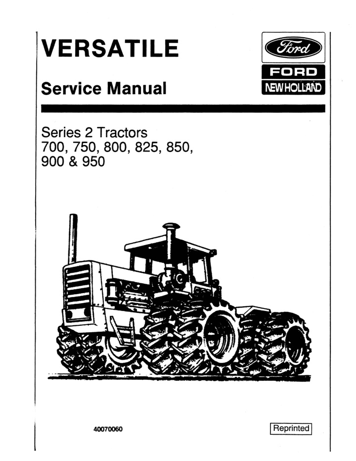
Ford Versatile 900 Series 2 Tractor Service Repair Manual Instant Download
Ford Versatile 900 Series 2 Tractor Service Repair Manual Instant Download
Download Presentation

Please find below an Image/Link to download the presentation.
The content on the website is provided AS IS for your information and personal use only. It may not be sold, licensed, or shared on other websites without obtaining consent from the author. If you encounter any issues during the download, it is possible that the publisher has removed the file from their server.
You are allowed to download the files provided on this website for personal or commercial use, subject to the condition that they are used lawfully. All files are the property of their respective owners.
The content on the website is provided AS IS for your information and personal use only. It may not be sold, licensed, or shared on other websites without obtaining consent from the author.
E N D
Presentation Transcript
reB] FORD I\EWHOLtMD VERSATILE Service Manual Series 2 Tractors 700,750,800,825,850, 900 & 950 I Reprinted I 40070060
service manual SERIES 2 FOUR-WHEEL DRIVE TRACTORS APPLICABILITY: For 1977 Model Year Tractors. Certain sections of this manual will also be applicable, in whole or in part, to preceding model years. The serviceman should read the table of contents to deter- mine specific applicability. APPLICABILITY: FOR 1977 MODEL YEAR TRACTORS. CERTAIN SECTIONS OF THIS MANUAL WILL ALSO BE APPLICABLE, IN WHOLE OR IN PART, TO PRECEDING MODEL YEARS. THE SERVICEMAN SHOULD READ THE TABLE OF CONTENTS TO DETERMINE SPECIFIC APPLICABILITY. Date of Issue, First Edition: 5 JUNE 1978 PU4001
FOREWORD This Service Manual is issued to provide sufficient instructions for a qualified service mechanic to carry out Basic Servicing, Troubleshooting, Maintenance (removal, inspection and replacement of component as- semblies,) and Overhaul (disassembly, inspection, repair and replacement of sub-assemblies). A summary of the contents of each Section is provided in the main Table of Contents and a detailed coverage will be found in the Table of Contents preceding each Section. The Service Manual should be used in conjunction with the Parts Manual for the specific Model year of Tractor. For the Serviceman's convenience and for reference to engine data and service, a list of Cummins Distributors is provided as Appendix 1 following Section 8: Structures. REVISIONS AND ADDITIONS TO THE MANUAL When changes are made in the unit covered in this service manual, pages will be marked to indicate whether they are replacement, or added pages. Replacement pages will show the revision number and carry the same page number as the original issue.oiscard the originalpageand insert the replacement page in its place. Added pages will carry the revision number, an existing page number, and an alphabetical suffix (for example A, B, etc.). Insert these pages after the existing page. A new revision record page will also be issued with every update as a check sheet so that the reader can deter- mine if the manual is complete. The purpose of a loose-leaf Service Manual is to enable us to keep the book updated, and to revise it if it is found necessary to provide additional information. This purpose will be defeated if additional or revised pages are supplied. Please insert them immediately. A 'feed-back' page has been inserted at the back of this Service Manual. After using this book, it would be ap- preciated if the user fills in this form and returns it to Versatile Manufacturing Limited. Such information will help us to improve our manuals if required, and gived the user better manuals in the future.
https://www.ebooklibonline.com Hello dear friend! Thank you very much for reading. Enter the link into your browser. The full manual is available for immediate download. https://www.ebooklibonline.com
SECTION 1: SERVICING
SECTION 1: SERVICING Table of Contents 1 2 2. 1 2.2 2.3 3 3.1 3.2 . 3.3 4 4.1 4.2 4.3 4.4 4.5 4.6 4.7 4.8 4.9 4.10 4.11 4.12 4.13 4.14 4.15 4.16 4.17 4.18 4.19 4.20 4.21 4.22 4.23 4.24 4.25 5 5.1 5.2 5.3 INTRODUCTION TOWINGITRANSPORTING General .... ,. . . . . . . . . . . . . . . . . . . . . . . . . . . . . . . . . . . . . . Towing. . . . . . . . . . . . . . . . . . . . . . . . . . . . . . . . . . . . . . . . . . . . Transporting. . . . . . . . . . . . . . . . . . . . . . . . . . . . . . . . . . . . . . . HOISTS AND JACKS General . . . . . . . . . . . . . . . . . . . . . . . . . . . . . . . . . . . . . . . . . . . Jacks . . . . . . . . . . . . . . . . . . . . . . . . . . . . . . . . . . . . . . . . . . . . . Hoists .................................... ....... . SPECIFICATIONS AND CAPACITIES General ........................................... 1-4 Dimensions. . . . . . . . . . . . . . . . . . . . . . . . . . . . . . . . . . . . . . . . Tire Size and Tractor Width . . . . . . . . . . . . . . . . . . . . . . . . . . . Tire Inflation. . . . . . . . . . . . . . . . . . . . . . . . . . . . . . . . . . . . . . . Weights. . . . . . . . . . . . . . . . . . . . . . . . . . . . . . . . . . . . . . . . . . . Engines. . . . . . . . . . . . . . . . . . . . . . . . . . . . . . . . . . . . . . . . . . . Cooling System .................................... 1-7 Air Cleaner. . . . . . . . . . . . . . . . . . . . . . . . . . . . . . . . . . . . . . . . . Exhaust System. . . . . . . . . . . . . . . . . . . . . . . . . . . . . . . . . . . . Cold Start Aid . .... ......... ............. ...... ..... Clutch ...... . . . . . . . . . . . . . . . . . . . . . . . . . . . . . . . . . . . . . . Brakes. . . . . . . . . . . . . . . . . . . . . . .. . . .. . . . . . . . . . . . . . . . . Transmission ...................................... 1-7 Drivelines .. . . . . . . . . . . . . . . . . . . . . . . . . . . . . . . . . . . . . . . . Axles............................................. Steering... ........................................ 1-8 Hydraulic System. . . . . .. . . . . . . . . . .. . . .. .. . .. . . . . . . . . Electrical System................................... Frames. . . . . . . . . . . . . . . . . . . . . . . . . .. . . . . . . . .. . . . .. . . . Drawbar . . . . . . . . . . . . . . . . . . . . . . . . . . . . . . . . . . . . . . . . . . . Cab. . . . . . .. . . . . . . . . . . . . . . . . . . . . . . . . . . . . . . . . . . . . . . . Instrument Panel. . . . . . . . . . . . . . . . . . . . . . . . . . . . . . . . . . . Environmental Control Roof Unit. . . . . . . . . . . . . . . . . . . . . . Radio. . . . . . . . . . . . . . . . . . . . . . . . . . . . . . . . . . . . . . . . . . . . . Options. . . . . . . . . . . . . . . . . . . . . . . . . . . . . . . . . . . . . . . . . . . FUELS, FLUIDS AND LUBRICANTS General ..... . . . . . . . . . . . . . . . . . . . . . . . . . . . . . . . . . . . . . . Fuel. . . . . . . . . . . . . . . . . . . . . . . . . . . . . . . . . . . . . . . . . . . . . . Fluids. . . . . . . . . . . . . . . . . . . . . . . . . . . . . . . . . . . . . . . . . . . . . 1-3 1-3 1-3 1-3 1-4 1-4 1-4 1-5 1-5 1-5 1-5 1-7 1-7 1-7 1-7 1-7 1-7 1-8 1-8 1-8 1-8 1-8 1-8 1-9 1-9 1-9 1-9 1 9 1-9 1-10
5.4 6 6.1 7 7.1 7.2 7.3 8 8.1 8.2 Lubricants. . . . . . . . . . . . . . . . . . . . . . . . . . . . . . . . . . . . . . . . . LUBRICATION General .. . . . . . . ..... . . . . . . . .. . . ..... .. . . . . . . .. .. . . BELTS AND FILTERS General... . . . . . . . . . . . . . . . .. . . . . . . .... . . . . . . . . . .. .. Belts-Replacement. . . . . . . . . . . . . . . . . . . . . . . . . . . . . . . . . Filters. . . . . . . . . . . . . . . . . . . . . . . . . . . . . . . . . . . . . . . . . . . . . STORAGE General. .. . . . . . . . . . . . . . . . .. . . . . . . . ... . . . . . . .. . . . . . Preparation of Tractor for Storage . . . . . . . . . . . . . . . . . . . . . Preparation of Engine for Storage ........... . . ...... . . Storing Batteries. . . . . . . . . . . . . . . . . . . . . . . . . . . . . . . . . . . . Preparation after Storage. . . . . . . . . . . . . . . . . . . . . . . . . . . . . Startup of Engine after Storage. . . . . . . . . . . . . . . . . . . . . . . . TROUBLESHOOTING General... . . . . . . . . . . . . . . . . . . . . . . . . ... . . . . . . .. . . . . . Troubleshooting Guide. . . . . . . . . . . . . . .. . . . . . . . . . . . . . . Troubleshooting Drive Train. . . . . . . . . . . . . . . . . . . . . . . . . . Hydraulics. . .. . . . . . . . . . . . . . . . . . . . .. . .. . . . . . . . . . . . . . Troubleshooting Electrical System. . . . . . . . . . . . . . . . . . . . Troubleshooting Environmental' System. . . . . . . . . . . . . . . . 1-10 1-11 1-15 1-15 1-15 1-15 1-15 1-16 1-16 1-19 1-19 - 8.3 8.4 8.5 8.6 9 9.1 9.2 9.3 9.4 9.5 9.6 1-19 1-20 1-22 1-24 1-26 1-29
SERVICING SECTION 1: 1 Introduction 4. Use a strong front end loader to pick up either front or rear of tractor and push (and ar- ticulate) into the service area. Disconnect drivelines when transmission or axles need repair or overhaul. When axle is broken, remove side covers from the planetary hubs and pull planetaries out. Cover the exhaust stack on all turbocharged tractors to prevent the turbocharger seizing. This applies when engine can not be started. This section contains general information about specifications, capacities, lubricants, fluids and fuels for the tractor as a whole rather than having the information scattered throughout the other sec- tions. A troubleshooting subsection will make reference to other service sections in the manual, which cover the tractor in greater detail. 5. 6. 7. 2 Towing/Transporting 2.1 GENERAL 2.3 TRANSPORTING Towing or transporting a large four wheel drive tractor is a big job. Below are listed some recom- mendations to follow. For long distances, hauling the tractor on a trailer is best. Use the following Procedures when hauling the tractor: 1. Check with local authorities as to laws, permits required and other information required to transport large machinery. 2. Use a trailer having the carrying capacity (30,0- 00 Ibs.) to haul tractors and other large machinery. 3. Use "wide load" signs and equip trailer with clearance lights to indicate to passersby of load. 4. Equip the trailer with a winch (minimum 10-ton capacity) to pull tractor on to the trailer. 5. Securely chain tractor to trailer to prevent trac- tor movement or tipping. 6. Block wheels and / or engage park brake to prevent tractor movement. 7. Inspect chains regularly looking for cracks, gouges, wear, bent links, worn or bent hooks. Repair any damaged links and hooks. 8. Cover the exhaust pipe on all turbocharged tractors to prevent the turbocharger seizing. 2.2 TOWING Use the following recommendations when towing is necessary: 1. Use a strong chain, cable or towbar and attach securely to the front plate or drawbar of tractor. 2. Let engine run, if possible, so full use is made of hydrostatic steering. 3. Tow tractor slowly to allow operator to properly control towed unit. NOTE If engine can not be started, pull tractor in a gradual arc across the field. Steering tractor will be dif- ficult. CAUTION--------- DO NOT TOW TRACTOR FASTER THAN 10 MPH (17 km/hr.) DO NOT SLIDE TRACTOR FROM SIDE TO SIDE TO MAN- EUVER INTO PLACE FOR REPAIR, DAMAGE TO DRIVE- TRAIN WILL RESULT. 3 Hoist and Jacks 3.1 GENERAL Hoist and jacks are most useful in properly servic- ing the tractor. Use the following recommendations to aid in safely working on the tractor or any other equipment. BE ALERT 1-3
3.2 JACKS Improper use of jacks or lifting devices results in serious accidents. Use the following recommenda- tions when raising tractor using a jack: 1. Select a jack strong enough to carry the load. The minimum jack required is five ton capacity. 2. Use jack carefully. Dropping or tossing dis- torts or cracks the jack housing causing jack to fail. 3. Take proper care of jack by using proper lubricants as specified in the operating in- structions. Do not use leaky jacks to lift heavy equipment. 4. Stabilize tractor by placing transmission into gear; engaging park brake; chocking or blocking wheels securely. 5. Brace up the center pivot frame by applying a strong wedge on the frame pivot to prevent jackknifing of tractor. and injuries. These accidents are caused by overloading the hoist or rigging the lift chains so they slip. Practice the- following: 1. Use a proper chain hoist and frame to properly lift tractor. The minimum capacity required for the hoist is ten tons; for the A-frame or overhead support is seven and one-half tons; and for the support stands is three tons. 2. Never overload a hoist or kame beyond its car- rying capacity. 3. Inspect chains regularly looking for cracks, gouges, wear, or bent links. Repair any damaged links. 4. Inspect hooks regularly and replace any that are bent, cracked, spring or worn. If in doubt, compare the dimensions of a new hook with the old one. Replace if there are any dif- ferences in the size or shape. 5. Select suitable, balanced lift point on tractor frame. Place hook and frame directly over the pOint of lift. 6. ?et chain to prevent the pull pOint from slipp- mg. 7. Protect yourself from injury as tractor is being raised by doing the following: 6. Use a level ground or floor surface so jack will lift straight up and down. 7. Place jack securely under axle tube, frame, or drawbar where it is strong enough to support the lifted weight. Use a heavy block as a base for the jack if working on ground. It should be long and wide enough to keep jack from tipping, sink- ing or shifting. Any additional blocking should be under the jack. Jack up front and/or rear frame just enough to install steel safety stands under axle tubes or frame. Check jack position after it has started to lift. Lower jack immediately if it starts to lean. Reset jack; block tractor more securely and lift again. Keep tractor stable by not raising so high it will slide off jack saddle. Remove jack handle from mechanical jacks, when not in use, to prevent being stuck by handle. a) b) Do not stand on tractor as you are lifting. Keep hands away from pinch points where chain links tighten or chain is against trac- tor frame. 8. c) Do not let tractor swing and strike person- nel or fame as it leaves the ground. Keep support stands nearby and place un- der tractor when proper height is reached. 9. d) 10. e) Do not go under tractor supported by a chain hoist. Place support stands under tractor before working under tractor. 4 Specifications and Capacities 11. 4.1 The specifications and capacities apply to the Models 700, 750, 800, 825, 850, 900, 950 Series 2 tractors. GENERAL 12. 13. Hold handle of mechanical jack firmly to pre- vent kicking as tractor is being raised or lowered. Place support stands under tractor. Lower jack and let tractor rest on stands. This provides a solid support for the tractor when jack is removed. 4.2 Wheel Base - 130 in. Tread, with 20.8 x 38 single tires - 72 in. between centers. Overall length - 253 in. without three-point hitch Overall width - 93 in. with 20.8 x 38 single tires Cab height - with 20.8 x 38 single tires Models 700, 750, 800, 825: 125 in. Models 850,900,950: 126-3/4 in. DIMENSIONS 14. 3.3 Improper hOisting 6'luipment can create accidents HOISTS 1-4
4.4 TIRE INFLATION For proper tire inflation, follow the recommenda- tions listed (Ref. Table 1-1). IMPORTANT Outside tires (duals) should have 2 psi Ie.. pressure than the Inside tires. Maximum allowable height - (Clearance for Bridges, Overpasses, etc.) - with 20.8 x 38 Single Tires, and with antenna vertical and adjusted to 30 in. height: Models 700, 750, 800, 825: 156 in. Models 850, 900, 950: 156-3/4 in. Turning Radius: 236 in. with 18.4 x 38 Dual tires 239 in. with 20.8 Dual tires 216 in. with 24.5 x 32 Single tires 222 in. with 30.5 x 32 Single tires Nominal - 203.5 in. measured to center line of 72 in. tread. 4.5 WEIGHTS Table 1-2 lists the weights of Series 2 tractors in shipping weight, maximum operating and recom- mended range. 4.3 TIRE SIZE AND TRACTOR WIDTH 4.6 ENGINES Tractor width (Outside of tires): Model 700 Cummins V-555-C210 V8 diesel Maximum brake horsepower - 210 @ 2850 rpm (per SAE Standard J816a) Maximum torque - 425 Ib ft @ 1800 rpm Full load governed speed - 2850 rpm Full throttle no load speed - 3100 to 3135 rpm Idle speed - 1000 rpm Bore - 4.625 in. Stroke - 4.125 in. Displacement - 555 cu. in. Compression ratio - 17.0:1 Lubrication system - 26 U.S. qts., 21.7 Imp. qts. Full flow oil filter with by-pass oil conditioner, filter and oil to water cooler 300 angular capability oil pan Mounts - VERSATILE design, fully rubber mounted. -Inner tires - 91.5 in. Outer tires - 137.5 in. 20.8 x 38 Dual tires Between tread centers: Inner tires - 72 in. Outer tires - 112 in. (Outside of tires): Inner tires - 93 in. Outer tires - 143.5 in. 24.5 x 32 Dual tires Between tread centers: Tractor Width (Outside of tires): 24.5 x 32 Single tires Between tread centers: Tractor width (Outside of tires): 30.5 x 32 Single tires Between tread centers: Tractor width (Outside of tires): 72 in. 97.5 in. 72 in. 97.5 in. 79.12 in. 109 in. TABLE 1-1: Tire Inflation Chart LITTLE OR NO BALLAST MAX BALLAST OR HEAVY LOAD PLY RATING TIRE SIZE 18.4 x 38 20.8 x 38 24.5 x32 30.5 x32 16 psi 16 psi 18 psi 16 psi 6 8 16 psi 20 psi 20 psi 16 psi 10 10 When used as duals, minimum tire pressure is 12 psi. Use ballast on duals only. 1-5
TABLE 1-2: Operating Weights 800 825 700 750 850 900 950 28,000 28,000 28,000 28,000 29,000 32,500 Maximum Operating Weight (Ibs.) Recommended Range of Operating Weights (Ibs.) Shipping Weight with 20.8 x 38 Tires (Ibs.) 22,500 to 25,000 23,000 25,000 24,000 26,000 26,000 27,500 27,000 28,500 29,300 31,000 16,920 18,020 18,100 18,380 17,920 18,045 For detailed recommendations of operating weights, consult Specifications Section of Operator's Manual for each Model. Full throttle no load speed - 2250 rpm to 2300 rpm Idle speed - 1000 rpm Bore - 5.50 in. Stroke - 6.00 in. Displacement - 855 cu. in. Lubrication system - 41 U.S. qts . 34.6 Imp. qts. Full flow oil filter with by-pass oil conditioner filter and oil to water cooler 300 angularity capability oil pan Mounts - VERSATILE design, fully isolated Model 750 Cummins N-855-C220 (in-line six cylinder) diesel Maximum brake horsepower - 220 @ 2100 rpm (per SAE Standard J-816a) Maximum torque - 644 Ib ft @ 1500 rpm Compression ratio - 15.8:1 Model 800 Cummins N-855-C235 (in-line six cylinder) Maximum brake horsepower - 235 @ 2100 rpm (per SAE Standard J-816a) Maximum torque - 660 Ib ft @ 1500 rpm Compression ratio - 15.8:1 Model 900 Cummins V-903-C-295 V8 diesel Maximum brake horsepower - 295 @ 2400 rpm (per SAE Standard J-816a) Maximum torque - 706 Ib ft @ 1800 rpm Compression ratio - 16.5:1 Model 825 Cummins NT-855-C250 (in-line six cylinder) Maximum brake horsepower - 250 @ 2100 rpm (per SAE Standard J-816a) Maximum torque 750 Ib ft @ 1500 rpm Compression ratio - 15.8:1 Model 950 Cummins VT -903 V8 diesel Turbocharged Maximum brake horsepower - 348 @ 2400 rpm (per SAE Standard J-816a) Maximum torque - 848 Ib ft @ 1800 rpm Compression ratio - 15.5:1 Model 850 Cummins NT -855-C280 (in-line six cylinder) Maximum brake horsepower - 280@ 2100 rpm (per SAE Standard J-816a) Maximum torque - 806 Ib ft @ 1500 rpm Compression ratio - 14.0:1 Common Specifications for V-8 engine (Models 900 and 950 Tractors) Full load governed speed - 2400 rpm Full throttle no load speed - 2550 rpm to 2640 rpm Idle speed - 1000 rpm Common Specifications for 855 Engine (Models 750, 800, 825. 850 Tractors) Full load governed speed - 2100 rpm 1-6
Type - Ether, operated from instrument panel Bore - 5.50 in. Stroke - 4.75 in. Displacement - 903 cu. in. Lubrication system - 34 U.S. qts., 28.3 Imp. qts. Full flow oil filter with by-pass oil conditioner and oil to water cooler. 300 angular capability oil pan Mounts - VERSATILE design, fully isolated 4.11 Dana Spicer - 14 in. two plate dry type, self- adjusting Model AS-1402 (Model AS2-1402SD, Model 950 only) pull type with angle spring Spring loaded, cushion hub discs Ceramic button linings Greaseable shaft bearing with slinger and sealed release bearing Foot operated, mechanically actuated Integral disc type, torque limiting transmission brake Static torque rating - 16.40 Ib ft CLUTCH 4.7 Capacity: Model 700 - 48 U.S. qts., 40 Imp. qts. Models 750, 800, 825, 850 - 49 U.S. qts., 41 Imp. qts. Models 900, 950, - 53 U.S. qts., 42 Imp. qts. Radiator (4-row core) rubber mounted. Model 700 - 750 sq. in. All others - 930 sq. in. Independent surge tank. Quickly removable perforated metal grill screen fan (6-blade sucker type). Model 700 - 24 in. diameter. Models 750, 800 - 26 in. diameter. Models 825, 850, 900, 950 - 28 in. diameter. COOLING SYSTEM 4.12 BRAKES Road Brake - driveline mounted, 15 in. disc and self-adjusting caliper, hydraulically actuated by a single foot pedal. Park Brake - same disc with caliper mechanically actuated by over center lever. 4.13 TRANSMISSION VERSATILE design, completely rubber mounted 12 speed constant mesh with sliding collar shifting 4 shafts vertically arranged, 3.0 in. diameter, drilled for lubrication. Independent lubrication system with pump, 10 micron filter, cooler, steel lines and wire braid hose, dash mounted oil pressure warning light. Oil capacity - 21 .5 U.S. qts., 16.8 Imp. qts. Dipstick oil level check and filler point Timken tapered roller bearings Helical forward gears with straight cut (spur) reverse gears One dash mounted, in-line shift, range lever One floor mounted gear shift lever Each model has five field speeds between: - Model 700 - 4.1 and 7.5 mph - Models 750, 800 & 825 - 4.1 and 7.3 mph - Model 850 - 4.1 and 7.3 mph - Models 900 & 950 - 4.0 and 7.2 mph 4.8 Models 700, 750, 800 and 900: United-Triphase (700 Model E112D18; 750, 800, 900-Model 114010) Models 825, 850, 950: Donaldson Strata System STB14-0019 Both United and Donaldson systems: Dual element, dry type with safety element Restriction indication gauge on instrument panel AIR CLEANER 4.9 Model 700 - One 8.5 in. diameter x 36 in. muffler Models 750, 800, 825, 850, 950 - One 8.25 in. x 11.5 in. elliptical x 40 in. muffler. Models 750, 800, 825, 850, 950 - One 8.25 in. x 11.5 in. elliptical x 40 in. muffler. Model 900 - Two 8.5 in. diameter x 35.3 in. mufflers. Mufflers are rubber-mounted .. Built-in vacuum aspirator for air cleaner. Built-in spark arrestor (where mandatory). EXHAUST SYSTEM 4.14 Engine to transmission - Spicer 1550 Series (Model 950 - Spicer 1600 Series) Transmission to axles - Spicer 1600 Series DRIVELINES 4.10 Make - KBI COLD START AID 1-7
TABLE 1-3: Speed. in Mil per Hour 700 2850 rpm 850 2100 rpm 750,800,8252100 rpm MODEL 900 "950 2400 rpm 4 1 4 1 2 1 2 3 4 2 3 3 Range 1 2 3 4 3.1 3.5 4.1 3.5 Low Gear Second Gear High Gear Reverse 2.6 2.6 3.0 4.1 2.6 3.0 4.1 3.5 2.5 3.0 3.3 4.0 7.3 4.7 7.5 4.7 9.1 10.8 12.2 14.5 3.4 4.0 5.6 6.3 4.7 9.2 10.7 12.3 14.3 . 9.2 10.7 12.3 14.3 3.4 3.9 4.5 5.2 5.5 6.3 5.5 6.3 7.3 4.5 8.8 10.5 11.7 14.1 3.3 3.9 5.4 6.0 7.2 4.5 5.3 3.4 3.9 4.5 5.2 4.3 5.2 NOTE: All speeds are with 24.5 x 32 tires (31.5 in. loaded radius tires). Spicer Glidecote telescoping action Driveline carrier bearing on center swing frame Reservoir - vented, 74.5 U.S. qts., (62 Imp. qts.) capacity Dipstick oil level check and low level sight glass 4.15 AXLES VERSATILE design Spiral bevel (and planetaries. on Models 850,900. 950) differential with outboard planetary floating ring gear final drive. Eaton differential - (Models 700, 750, 800. 825 - Series 17103. Models 850, 900, 950 - Series 23120) Differential housing and axle tubes - Ductile iron Oil Capacity - Models 700. 750. 800. 825 - 38 U.S. qts., 31.6 Imp. qts . Models 850. 900, 950 - 40.4 U.S. qts . 34.0 Imp. qts. Lubrication - SAE 90 MIL 2105 B gear oil Axle seals - Unitized (combined neoprene seal and wear sleeve), prelubricated labyrinth-type guard. Wheel mounting bolts - Twelve. 0.75 in. diameter 4.18 ELECTRICAL SYSTEM 12 volt - negative ground system 12 volt - 75 amp Delco-Remy alternator Two 80-900 amp 12 volt batteries, connected in parallel inside clean compartment AWG 00 starting cables Circuit breakers - automatic resetting type Fuses - accessible and identified Six 60 watt working lights (exceeds ASAE 279.6) Two red tail lamps for highway (ASAE 279.6) 4.19 Articulated frame 4-wheel drive Oscillates to 15 degrees in both directions Front frame - 3/8 in. formed side plates with 1/2 in. rear end plate. Reinforcement near axle mounting pads Rear frame - 1/2 in. formed plate FRAME 4.16 STEERING Articulated frame - 42 degrees in each direction Fully hydrostatic actuation Two 3 in. 1.0. x 16.5 in. stroke actuators mounted with 1.25 in. self-aligning ball bushings. .4.20 DRAWBAR Swinging clevis type - 1.75 in. x 5.0 in. steel with wear block, 1.5 in. hardened steel pin with locking lever. Replaceable hardened bushings Height - 18 in. to top of main member 4.17 HYDRAULIC SYSTEM Pump gear type. Flow: Model 700 - 25 U.S. gpm. Models 750. 800. 825, 850 - 23.5 U.S. gpm, Models 900, 950 - 26.9 U.S. gpm. Drive - engine mounted gear driven Relief valve - set at 2300 - 50 psi Two-way spools which self-cancel at 2100 - 0 to 100 psi One four-way spool with float position 4.21 VERSATILE design - independent module type with rollover protective structure (ASAE 5336.1) Fully isolated on rubber mounts CAB 1-8
Acoustically insulated interior tinted safety glass, side windows open for emergency exit Height - 63 in. outside Width - 56 in. outside Lap type seat belt, easily adjustable Bostrom seat, fully adjustable. Some '76 models have swivel seat. Self-cleaning cab air filter allows for longer periods between manual servicing. The filter is removable (without the use of tools) from outside the cab. 4.24 (1977 Models) AM-FM (stereo) - 2 speakers Make - automatic radio Solid state circuitry Five push button station selection Volume and tone controls Telescoping antenna, spring mounted RADIO (1976 Models) AM Solid state Radio Five push button station selection Volume and tone controls Telescoping antenna, spring mounted 4.22 INSTRUMENT PANEL Gauges - engine tachometer with hour meter; engine oil pressure; engine temperature; battery condition voltmeter; fuel level Warning lights - transmission oil pressure; park brake; alternator Key ignition Manual override button for automatic shut down system Hazard warning-signal flasher combination Light switch Ether cold start aid control International identification symbols on gauges and warning lights (ASAE S303.4) OPTIONS 4.25 No-spin differential - front axle only or front and rear axles. Rear fenders Three-point hitch (category III) - lift capacity of 12,370 Ibs. at 24 in. to the rear of the lower link points throughout the working range. Maximum lift is 18,270 Ibs. at the lift pOints. Quick-attach coupler for three-point hitch Tires - singles - 24.5 x 32, 30.5 x 32 duals - 18.4 x 38, 20.8 x 38 Rice and Cane Tires - 24.5 x 32 singles (Goodyear and Firestone) 30.5 x 32 singles (Goodyear and Firestone) Dual wheel spacer - 14 in. for 18.4 x 38 tires Engine block heater 4.23 VERSATILE design Operator controlled recirculation door - provides cool inside air recirculation to reduce heat load on air conditioning system, without losing cab pres- surization 24,000 BTU/hr. air conditioning evaporator core to cool cab air and remove humidity Large heater to warm cab and defrost windshield Automatic shut down of compressor if refrigeration system becomes low on freon, or if pressure becomes too high Indicator lights to indicate reasons for shut down Pressurization and recirculation fan, 3-speed selection Fan automatically comes on when ignition key is turned on to prevent operation of tractor without cab pressurization ENVIRONMENTAL CONTROL ROOF UNIT 5 Fuels, Fluids and Lubricants 5.1 The following information lists fuels, fluids and lubricants used on the Series 2 Tractors. Also lubri- cant capacities for the various models are listed. GENERAL 5.2 No.2 diesel fuel is recommended. No.1 diesel fuel is also satisfactory. Any other fuel should meet the following specifications: Sulfur content less than one per cent. Sediment and water content less than 0.1 per cent FUEL 1-9
Coolant Conditioner Filter: (Dry Chemical Additive) used when coolant is replaced. Engine Coolant Capacities - Model 700 - 48 U.S. qts., 40 Imp. qts. Models 750, 800, 825, 850 - 49 U.S. qts., 40.8 Imp. qts. Models 900, 950 - 53 U.S. qts., 44.1 Imp. qts. Cetane number 40 or greater. A higher Cetane number fuel may be required at low temperatures or high altitudes. Pour point below the lowest expected temperature Ash content less than 0.02 per cent Viscosity range 0.021 - 0.089 sq. in.lsec. at 1000 F. Fuel capacity - 185 U.S. gal., 154 Imp. gal. REFUELING Observe all cautions and warnings in the Operator's Manual. Refer to "Tractor Safety" (or "Safety Rules") and "Operation" section of Operator's Manual for more information on refuell- ing. Brake Fluid SAE specification 70R3. Hydraulic Fluid Temperatures above 400 F - Esso Hydraul 56 or SAE 20 MS Motor Oil Temperatures below 400 F - Dexron or 5W-20 MS Motor Oil 5.3 FLUIDS Coolant Mixture Water: Clean and preferably soft. Water suitable for drinking is adequate as a coolant. A BE ALERT Liquid Ballast The tire ballast consists of commercial Type 1 Calcium Chloride Flake (77 per cent CaCI2) mixed with water (Ref. Table 1-4). If Type 2 Flake (94 per cent CaCI2) is used, the weights given can be reduced by 25 per cent. The 3-1 12 Ib.l gal. Calcium Chloride Solution is slush-free to -120 F (-24.4 C) and freezes solid at - 52 F. The 51b.lgal. solution is slush-free to -52 F and will freeze solid at -62 F. - CAUTION --------- DO NOT USE DOW CHEMICAL THERM 209 BRAND AN- TIFREEZE. IT IS NOT COMPATI- BLE WITH THE CORROSION INHIBITOR. 5.4 LUBRICANTS Table 1-5 lists the recommended lubricants for the tractor used for varying temperature conditions. Antifreeze: Commercial grade, ethylene glycol base, used in proportions recommended by the manufacturer. TABLE 1-4: Liquid Ballast Calculations 3-1 12 LB. CaCI2 SOLUTION PER GAL 5 LB. CaCI2 SOLUTION PER GAL WATER ONLY WT LBS IMP GAL US GAL IMP GAL CaCI2 WEIGHT LBS TOTAL TOTAL US GAL IMP GAL CaCI2 WEIGHT LBS US GAL TIRE SIZE 18.4x 36 20.8 x 36 24.5x32 30.5 x32 110 140 170 217 94 120 146 186 78 329 lb. 100 420 lb. 122 511 lb. 155 651 lb. 917 1168 1418 1810 92 117 142 181 11131b. 1420 lb. 1729 lb. 2202 lb. 74 445 lb. 95 470 lb. 115 690 lb. 146 875 lb. 1190 lb. 1521 lb. 1841 lb. 2335 lb. 89 114 138 175 NOTE The amount of liquid required wi/l have to be determined as outlined in the calculation of wheel slippage given in the Operator's Manual. 1-10
TABLE 1-5: Lubricant Chart LOCATION CONDITIONS GRADE TYPE Oils Above 400 F (_40 C) 200 F to 600 F (_70 C to 160 C) -100 F to 300 F (-230 C to _10 C) Below -100 F (-230 C) Engine Crankcase SAE30 SAE20-20W CC/CD CC/CD 10W CC/CD See 'Arctic Oil Recom mendations' in Cummins Manual Above 400 F (40 C) Below 400 F (40 C) Transmission and Hydraulic System Hydraul56 or equivalent SO SAE5W-20 Above 900 F (320 C) Below 900 F (320 C) Differentials and Axle Planetary Gears SAE 140 SAE90 GL5 (MIL2105B)* or GL5 (MIL2105C)* Grea .. Pressure Grease Fittings All SAE High-Temperature Multi-Purpose * No Zinc Additives Models 750, 800, 825, 850 - 41 U.S. qts., 34.1 Imp. qts. Models 900, 950 - 34 U.S. qts., 28.3 Imp. qts. Hydraulic System - 74.5 U.S. qts., 28.3 Imp. qts. Transmission - 21.5 U.S. qts., 17.9 Imp. qts. Differential (each) Axle and two planetaries - 1976 All Models - 38 U.S. qts., 31.6 Imp. qts., 1977 Models 700, 750, 800, 825 - 38 U.S. qts., 31.6 Imp. qts.; 1977 Models 850, 900, 950 - 41 U.S. qts., 32.8 Imp. qts. Each planetary housing - 4 U.S. qts., 3.2 Imp. qts. American Petroleum Institute Lubricant Grades CC - Service typical of lightly supercharged diesel engines operating in moderate to severe duty. These oils provide protection from high temperature deposits. CD - Service typical of supercharged diesel engines in high output, high speed duty. These oils provide protection from bearing corrosion and high temperature deposits in supercharged engines using fuels of a wide quality range. NOTE Turbo-charged tractors require oil with the 'CD' classification. 8 Lubrication GL5(MIL2105B) or (MIL2105C) - Gear Lubricantfor service 'GLS (Hypoid Gears) meeting specification MIL210SB and MIL210SC with no zinc additives. 6.1 GENERAL Table 1-6 lists the lube pOints on the Series 2 trac- tors. Along with the table are lube point illustrations (Ref. Figure 1-1). Refer to subsection 5 for capacities and require- ments. Lubricant Capacities Engine Oil - Model 700 - 26 U.S. qts., 21.7 Imp. qts. 1-11
Suggest: If the above button click is invalid. Please download this document first, and then click the above link to download the complete manual. Thank you so much for reading
DIPSTICK Model 700 Model 900 Model 950 ENGINES 1976 - All Model. 1977 - Model. 700_, ____ 750, 800, 825 ~ _ FIGURE 1-1 Sheet 1 Lube Points 1-12
https://www.ebooklibonline.com Hello dear friend! Thank you very much for reading. Enter the link into your browser. The full manual is available for immediate download. https://www.ebooklibonline.com

