Frame Structure for Multi-hop Communications in IEEE 802.15 Standards
Explore the development of frame structures to facilitate multi-hop communications in IEEE 802.15 standards, focusing on MAC system design for the WPANs. The document discusses technical feasibility, proposed frame structures, and considerations for addressing the challenges of multi-hop operations.

Download Presentation

Please find below an Image/Link to download the presentation.
The content on the website is provided AS IS for your information and personal use only. It may not be sold, licensed, or shared on other websites without obtaining consent from the author. If you encounter any issues during the download, it is possible that the publisher has removed the file from their server.
You are allowed to download the files provided on this website for personal or commercial use, subject to the condition that they are used lawfully. All files are the property of their respective owners.
The content on the website is provided AS IS for your information and personal use only. It may not be sold, licensed, or shared on other websites without obtaining consent from the author.
E N D
Presentation Transcript
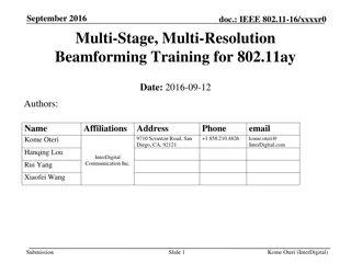
May 2014 doc.: IEEE 15-14-0257-00-0008 Project: IEEE P802.15 Working Group for Wireless Personal Area Networks (WPANs) Submission Title: [Frame Structure Supporting Multi-hop Communications for PAC] Date Submitted: [5 May 2014] Source: [Zhuo Chen, Hongkun Li, Qing Li, Chonggang Wang, Tao Han] Company [InterDigital Communications Corporation] Address [781 Third Avenue, King of Prussia, PA 19406-1409, USA] Voice:[610-878-5695], FAX: [610-878-7885], E-Mail:[Qing.Li@InterDigital.com] Re: [ Call for Final Contributions] Abstract: [This document presents frame structures including multi-hop communications on the PHY/MAC system design for 802.15.8 TG] Purpose: [To discuss technical feasibility of the proposed frame structures for multi-hop communications for 802.15.8 TG] Notice: discussion and is not binding on the contributing individual(s) or organization(s). The material in this document is subject to change in form and content after further study. The contributor(s) reserve(s) the right to add, amend or withdraw material contained herein. Release: The contributor acknowledges and accepts that this contribution becomes the property of IEEE and may be made publicly available by P802.15. This document has been prepared to assist the IEEE P802.15. It is offered as a basis for Slide 1 Submission ZC, HL, QL, CW, TH @InterDigital
May 2014 doc.: IEEE 15-14-0257-00-0008 Introduction (1/2) It s essential to develop a frame structure to fully support multi- hop operation at MAC, especially for distributed and infrastructure-less P2P networks (P2PNWs). Requirement in 802.15.8 TGD [1]: 5.2 Common communication mode: Common mode (e.g., for discovery and communication) shall be supported for interoperability. 6.11 Multi-hop Support: IEEE 802.15.8 shall provide at least 2- hop relaying function. Only relay-enabled PD shall relay discovery messages and/or traffic data from PDs in the proximity. Requirement in 802.15.8 PFD [2]: 5.14 Multi-hop Operation: To extend the coverage of a PD or group members, a PD or group members relay received data to the destination PD or group members. Slide 2 ZC, HL, QL, CW, TH @InterDigital Submission
May 2014 doc.: IEEE 15-14-0257-00-0008 Introduction (2/2) Existing frame structures in IEEE 802.11 and 802.15 standards for supporting multi-hop communications: 802.11 Contention free period and contention access period. Contention based access is simple but cause too many collisions to those P2PNWs with high density of PDs for both one-hop and multi-hop communications. 802.15.4 Most frame structures in 802.15.4 support only one-hop communications, which are not suitable for multi-hop communications for distributed and infrastructure-less P2PNWs. Slide 3 ZC, HL, QL, CW, TH @InterDigital Submission
May 2014 doc.: IEEE 15-14-0257-00-0008 Proposals Propose multi-hop frame structures with a dedicated multi-hop period. Proposed frame structure 1: a dedicated multi-hop period is inserted at the end of a Superframe. Proposed frame structure 2: a dedicated multi-hop period is inserted at the end of a frame. Propose multi-hop frame structures with time reuse. Proposed frame structure 1: Tier based frames structure for inter- Tier time reuse. Proposed frame structure 2: Sector based Hopper-subframe structure for intra-Tier time reuse. Slide 4 ZC, HL, QL, CW, TH @InterDigital Submission
May 2014 doc.: IEEE 15-14-0257-00-0008 Terms and Concepts PD: Peer Device Hopper: In the context of multi-hop, a PD that relays or hops a message/messages or data to the other PDs in proximity to extend the radio coverage. End PD: In the context of multi-hop, a PD that does not relay or hop any message or data to the other PDs in proximity. Initiator: The first PD to initiate the first service or application in proximity or the first PD to initiate a service or application in proximity. Tier: Ring based divisions of two-dimensional space to guarantee peers in non-adjacent Tiers do not interfere with each other. Sector: Angular divisions of Tiers to guarantee peers in non- adjacent sectors do not interfere with each other. Hop Distance: The number of hops between two peers. Slide 5 ZC, HL, QL, CW, TH @InterDigital Submission
May 2014 doc.: IEEE 15-14-0257-00-0008 Multi-hop Frame Structures with a Dedicated Multi-hop Period Motivations: To reduce the impact on one-hop communication, which may be required by many use cases in PAC. To reduce the contention and potential collision among different hops, especially for those high data rate and high QoS applications. To introduce more flexibility of frame formation for distributed P2PNW. Slide 6 ZC, HL, QL, CW, TH @InterDigital Submission
May 2014 doc.: IEEE 15-14-0257-00-0008 Frame Structure 1 Supporting Multi-hop Communication Superframe Beacon 1 Frame1 Beacon Frame2 Beacon Inactive SF Common Frame 1 Frame 2 Multi-hop Period One-hop Period Superframe A Superframe consists of : Superframe Beacon isto indicate the start of a Superframe and define the Superframe structure Superframe (SF) Common Period follows the Superframe Beacon, and is shared through contention based access One-hop Period contains a frame or multiple frames Multi-hop Period is dedicated for multi-hop P2P communications Inactive Period as the gap or guard time between Superframes Slide 7 ZC, HL, QL, CW, TH @InterDigital Submission
May 2014 doc.: IEEE 15-14-0257-00-0008 An Example of Frame Structure 1 Supporting Multi-hop Initiator A Hopper B 3 hops Hopper C End Peer D Time period that a peer is not aware of Transmission Reception Time period that a peer is aware of Frame Beacon Superframe Beacon Initiator A SF Common Frame 1 Frame 2 One-hop Period Multi-hop Period Hopper B and C communicate during this time period Hopper B Beacon Hopper B SF Common Frame 1 Frame 2 Hopper C Beacon Hopper C SF Common Frame 1 Frame 2 End Peer D SF Common Frame 1 Frame 2 Hopper C and End Peer D communicate during this time period Slide 8 ZC, HL, QL, CW, TH @InterDigital Submission
May 2014 doc.: IEEE 15-14-0257-00-0008 Frame Structure 2 Supporting Multi-hop Communication Frame 1 Beacon Frame Common Multi-hop period One-hop Period A Frame Superframe Beacon 1 Frame 1 Beacon Frame 2 Beacon Inactive Reserved SF Common Frame 1 Frame 2 Superframe A Superframe consists of : Superframe Beacon to indicate the start of the Superframe Superframe (SF) Common Period after the Superframe Beacon for inter- P2P communications A Frame or Frames for P2P communications, consisting of One-hop Period and Multi-hop Period Inactive Period as the gap or guard time between Superframes Slide 9 ZC, HL, QL, CW, TH @InterDigital Submission
May 2014 doc.: IEEE 15-14-0257-00-0008 An Example of Frame Structure 2 Supporting Multi-hop Initiator A Hopper B 3 hops Hopper C End Peer D Time period that a peer is not aware of Transmission Reception Time period that a peer is aware of Superframe Beacon Frame Beacon Initiator A SF Common Frame 1 Frame 2 Common Period One-hop Period Multi-hop Period Hopper B and C communicate during this time period Hopper B Beacon Hopper B SF Common Frame 1 Frame 2 Hopper C Beacon Hopper C SF Common Frame 1 Frame 2 Hopper C and End Peer D communicate during this time period End Peer D Frame 2 SF Common Frame 1 Slide 10 ZC, HL, QL, CW, TH @InterDigital Submission
May 2014 doc.: IEEE 15-14-0257-00-0008 Multi-hop Frame Structures with Time Reuse Motivations: To increase the capacity of the network. Slide 11 ZC, HL, QL, CW, TH @InterDigital Submission
May 2014 doc.: IEEE 15-14-0257-00-0008 Tier Based Frames Structure for Inter-Tier Time Reuse (1/2) Divide the two-dimensional space into Tiers. End Peer 1.1.1.1 Hopper 1.1.1 Hopper 1.1 Initiator 1 Tier 1 Tier 4 Tier 3 Tier 2 R Hopper 1.2 Hopper 1.2.1 R Hopper 1.2.1.1 End Peer 1.2.1.1.1 R R Slide 12 ZC, HL, QL, CW, TH @InterDigital Submission
May 2014 Tier Based Frames Structure for Inter- Tier Time Reuse (2/2) doc.: IEEE 15-14-0257-00-0008 A PD transmits within its Tier-frame. PDs in different Tiers that are far way can transmission simultaneously. Superframe Tier-frame 1, N+1, ... Tier-frame N-1, 2N-1, ... Tier-frame 0, N, ... ... End Peer 1.1.1.1 Reserved Overlapped Tier-frames Overlapped Tier-frames Overlapped Tier-frames Hopper 1.1.1 Hopper 1.1 Reuse the same Tier-frame 0 Initiator 1 time interval in air. Tier 1 Tier 4 Tier 3 Tier 2 Subframe 1 Reserved Hopper 1.2 R Hopper 1.2.1 Tier-frame N R Subframe 2 Ssubframe 3 Reserved Subframe 1 Hopper 1.2.1.1 ... End Peer 1.2.1.1.1 R R Slide 13 ZC, HL, QL, CW, TH @InterDigital Submission
May 2014 Sector Based Hopper-subframe Structure for Intra-Tier Time Reuse (1/2) Divide each Tier in to Sectors. doc.: IEEE 15-14-0257-00-0008 4,4 4,3 End Peer 1.1.1.1 4,5 4,2 3,4 3,3 3,5 3,2 Hopper 1.1.1 2,2 4,6 Hopper 1.1 1,2 2,3 4,1 3,6 2,1 3,1 1,3 1,1 Initiator 1 6 1,4 3,7 2,6 Hopper 1.2 1,5 2,4 3,12 4,7 4,12 Hopper 1.2.1 2,5 3,8 3,11 Hopper 1.2.1.1 End Peer 1.2.1.1.1 3,9 3,10 4,11 4,8 4,9 4,10 Slide 14 ZC, HL, QL, CW, TH @InterDigital Submission
May 2014 Sector Based Hopper-subframe Structure for Intra-Tier Time Reuse (2/2) doc.: IEEE 15-14-0257-00-0008 A PD transmits within its Hopper-subframe. PDs in different Sectors that are far way can transmit simultaneously. 4,4 4,3 A Tier-frame End Peer 1.1.1.1 Overlapped Hopper-subframes 4,5 Reserved 4,2 3,4 3,3 3,5 3,2 Hopper 1.1.1 2,2 Inter-Tier reuse A Tier-frame 4,6 Hopper 1.1 1,2 2,3 4,1 3,6 2,1 3,1 Hopper-subframe 5 Hopper-subframe 1 Hopper-subframe 4 unallocated 1,3 1,1 Initiator 1 unallocated Hopper-subframe 7 6 Hopper-subframe 2 1,4 3,7 2,6 Hopper 1.2 1,5 2,4 3,12 4,7 Hopper-subframe 6 unallocated Hopper-subframe 3 unallocated Hopper 1.2.1 4,12 2,5 3,8 3,11 Hopper 1.2.1.1 End Peer 1.2.1.1.1 3,9 3,10 4,11 4,8 4,9 4,10 Slide 15 ZC, HL, QL, CW, TH @InterDigital Submission
May 2014 An example with Inter-Tier and Intra- Tier Time Reuse doc.: IEEE 15-14-0257-00-0008 Time period that was not allocated to the peer Time period that was allocated to the peer Transmission Reception Initiator 1 Hopper 1.1 and Hopper 1.2 transmit during this time period Superframe Beacon Superframe Beacon Tier-frame 0/3 Tier-frame 2 Tier-frame 0 Tier-frame 1 Hoper-subframe 1 Initiator 1 Hoper-subframe 1 Initiator 1 Hopper 1.1 and Hopper 1.2 transmit during this time period Hopper 1.1 and Hopper 1.1.1 transmit during this time period Superframe Beacon 4,4 4,3 Hopper 1.1 Beacon Hopper 1.1 Hoper-subframe 1.1 Hoper-subframe 1 Hoper-subframe 1 End Peer 1.1.1.1 Hopper 1.2 and Hopper 1.2.1 transmit during this time period 4,5 4,2 3,4 3,3 Superframe Beacon Hopper 1.2 Beacon Hopper 1.2 3,5 3,2 Hoper-subframe 1.2 Hoper-subframe 1 Hoper-subframe 1 Hopper 1.1.1 Hopper 1.1.1 and End Peer 1.1.1.1 transmit during this time period 2,2 Hopper 1.1.1 Beacon Hopper 1.1 Beacon 4,6 Hopper 1.1 1,2 2,3 4,1 Hopper 1.1.1 3,6 2,1 Hoper-subframe 1.1 Hoper-subframe 1.1.1 3,1 1,3 1,1 Hopper 1.2.1 and Hopper 1.2.1.1 transmit during this time period Initiator 1 Hopper 1.2.1 Beacon Hopper 1.2 Beacon 6 1,4 Hopper 1.2.1 Hoper-subframe 1.2.1 Hoper-subframe 1.2 3,7 2,6 Hopper 1.2 1,5 2,4 3,12 4,7 4,12 Hopper 1.2.1 Hopper 1.1.1 Beacon 2,5 End Peer 1.1.1.1 3,8 3,11 Hopper 1.2.1.1 Hoper-subframe 1.1.1 Hopper 1.2.1.1 and End Peer 1.2.1.1.1 transmit during this time period End Peer 1.2.1.1.1 3,9 3,10 4,11 Hopper 1.2.1 Beacon Hopper 1.2.1.1 Beacon 4,8 Hopper 1.2.1.1 Hoper-subframe 1.2.1 Hoper-subframe 1.2.1.1 4,9 4,10 Hopper 1.2.1.1 Beacon End Peer 1.2.1.1.1 Hoper-subframe 1.2.1.1 Slide 16 ZC, HL, QL, CW, TH @InterDigital Submission
May 2014 doc.: IEEE 15-14-0257-00-0008 Simulation Result for Multi-hop Frame Structure with Time Reuse Slide 17 Submission ZC, HL, QL, CW, TH @InterDigital
May 2014 doc.: IEEE 15-14-0257-00-0008 General Configuration Topology: The Initiator is placed at the center of the area. Other PDs are randomly placed in the area. Hopper selection: A PD selects the neighboring PD with minimum hop distance to the Initiator. Forwarding model: A packet is forwarded to the destination via the shortest path. Slide 18 ZC, HL, QL, CW, TH @InterDigital Submission
May 2014 doc.: IEEE 15-14-0257-00-0008 Simulation Parameter Parameter Value Slot size 1 ms Packet size 128 bytes Simulation time 100 seconds Bandwidth 10 MHz Tx power 20 dBm Channel model (Path loss) As specified in TG8 Technical Guide. Metrics: Network Throughput (number of packets received at all destinations) Slide 19 ZC, HL, QL, CW, TH @InterDigital Submission
May 2014 doc.: IEEE 15-14-0257-00-0008 Use Case 1: Advertisement Merchant End Peer 4 Advertisement Customer End Peer 6 End Peer 2 Hopper 5 Hopper 3 Initiator 1 (Merchant) End Peer 5.3 Hopper 3.2 End Peer 5.2 End Peer 3.1 End Peer 5.1 End Peer 3.2.1 Slide 20 ZC, HL, QL, CW, TH @InterDigital Submission
May 2014 doc.: IEEE 15-14-0257-00-0008 Use Case 1 Configuration Frame structure: Each Hopper and the Initiator get 1 slot to transmit in each Superframe. Flow model: Only the initiator generates packets For each generated packet, random choose a PD in the network as the destination. Traffic model: Constant Bit Rate (CBR) traffic and full buffer Topology: Test Case 1: 150 PDs in 250*250 m2 area. (low PDs density in small area) Test Case 2 600 PDs in 500*500 m2 area. (low PDs density in large area) Test Case 3: 600 PDs in 250*250 m2 area. (High PDs density in small area) Test Case 4: 2400 PDs in 500*500 m2 area. (High PDs density in large area) Slide 21 ZC, HL, QL, CW, TH @InterDigital Submission
May 2014 doc.: IEEE 15-14-0257-00-0008 Network Throughput: Use Case 1 Number of packets received during 100s Test Case No reuse Inter-Tier Reuse only 2492.78 771.74 1337.96 440.92 Intra-Tier Reuse only 4169.44 1618.18 2266.72 918.96 Inter and Intra Tier Reuse 4466.72 3104.22 2335.14 1744.74 1 2 3 4 2382.9 511.28 1315.2 286.32 Observations: Multi-hop frame structure with time reuse increases the capacity of the network by Almost two times for smaller area networks 6 times for larger area networks Sector based Intra-Tier time reuse performs better than Tier based Inter- Tier time reuse especially in smaller area networks. Tier based Inter-Tier timer reuse performs better in larger area networks. Slide 22 ZC, HL, QL, CW, TH @InterDigital Submission
May 2014 doc.: IEEE 15-14-0257-00-0008 Use Case 2 (Emergency Service) Emergency service End Peer 4 End Peer 2 Hopper 5 Hopper 3 Initiator 1 End Peer 5.3 Hopper 3.2 End Peer 5.2 End Peer 3.1 End Peer 5.1 End Peer 3.2.1 Slide 23 ZC, HL, QL, CW, TH @InterDigital Submission
May 2014 doc.: IEEE 15-14-0257-00-0008 Use Case 2 Configuration Frame structure: Each PD gets 1 slot to transmit in each Superframe. Flow model: Randomly choose 10 source and destination pairs. Traffic model: Constant Bit Rate (CBR) traffic and full buffer Topology: Test Case 1: 150 PDs in 250*250 m2 area. (low PDs density in small area) Test Case 2 600 PDs in 500 *500 m2 area. (low PDs density in large area) Test Case 3: 600 PDs in 250*250 m2 area. (High PDs density in small area) Test Case 4 2400 PDs in 500 *500 m2 area. (High PDs density in large area) Slide 24 ZC, HL, QL, CW, TH @InterDigital Submission
May 2014 doc.: IEEE 15-14-0257-00-0008 Network Throughput: Use Case 2 (1/2) Number of packets received during 100s 12000 12000 Inter- and Intra-Tier Reuse Intra-Tier Reuse Only Inter-Tier Reuse Only No Reuse Inter- and Intra-Tier Reuse Intra-Tier Reuse Only Inter-Tier Reuse Only No Reuse Total number of packets received 10000 10000 Total number of packets received 8000 8000 6000 6000 4000 4000 2000 2000 0 0 0 5 10 15 20 25 30 0 5 10 Number of active flows 15 20 25 30 Number of active flows Test Case 1: 150 PDs in 250*250 m2 area Observations: Multi-hop frame structure with time reuse increases the capacity of the network by Almost two times for smaller area networks 5 times for larger area networks Test Case 2: 600 PDs in 500 *500 m2 area. Slide 25 ZC, HL, QL, CW, TH @InterDigital Submission
May 2014 doc.: IEEE 15-14-0257-00-0008 Network Throughput: Use Case 2 (2/2) Number of packets received during 100s 4000 Inter- and Intra-Tier Reuse Intra-Tier Reuse Only Inter-Tier Reuse Only No Reuse 4000 Inter- and Intra-Tier Reuse Intra-Tier Reuse Only Inter-Tier Reuse Only No Reuse 3500 3500 Total number of packets received Total number of packets received 3000 3000 2500 2500 2000 2000 1500 1500 1000 1000 500 500 0 0 0 5 10 15 20 25 30 0 5 10 Number of active flows 15 20 25 30 Number of active flows Test Case 3: 600 PDs in 250*250 m2 area Observations: Sector based Intra-Tier time reuse performs better than Tier based Inter- Tier time reuse especially in smaller area networks. Tier based Inter-Tier timer reuse performs better in larger area networks. Test Case 4: 2400 PDs in 500 *500 m2 area. Slide 26 ZC, HL, QL, CW, TH @InterDigital Submission
May 2014 doc.: IEEE 15-14-0257-00-0008 Conclusion To reduce the impact of multi-hop communications on one-hop communications, as well as the potential collisions, we propose 2 frame structures to support multi-hop communications for PAC. To increase the capacity of multi-hop communications, we propose to divide the two-dimensional space into several areas to achieve time reuse for multi-hop communications for PAC. Slide 27 ZC, HL, QL, CW, TH @InterDigital Submission
May 2014 doc.: IEEE 15-14-0257-00-0008 References [1] PAC TGD: 15-12-0568-08-0008-tg8-technical- guidance-document [2] PAC PFD: 15-14-0085-01-0008-tg8-pac- framework-document [3] PAC: 15-14-0258-00-0008-Multi-hop-Frame- Structure-Document-for-Final-Contribution Slide 28 ZC, HL, QL, CW, TH @InterDigital Submission