Function of Schmitt Trigger Circuits
Learn about the Schmitt Trigger, a logic input type that provides hysteresis to avoid errors in noisy input signals. Discover how it converts various waveforms into clean square waves and explore the circuit configurations and equations involved.

Download Presentation

Please find below an Image/Link to download the presentation.
The content on the website is provided AS IS for your information and personal use only. It may not be sold, licensed, or shared on other websites without obtaining consent from the author. If you encounter any issues during the download, it is possible that the publisher has removed the file from their server.
You are allowed to download the files provided on this website for personal or commercial use, subject to the condition that they are used lawfully. All files are the property of their respective owners.
The content on the website is provided AS IS for your information and personal use only. It may not be sold, licensed, or shared on other websites without obtaining consent from the author.
E N D
Presentation Transcript
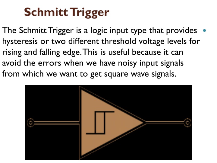
The Schmitt Trigger is a logic input type that provides hysteresis or two different threshold voltage levels for rising and falling edge. This is useful because it can avoid the errors when we have noisy input signals from which we want to get square wave signals.
So for example, if we have a noisy input signal like this, that is meant to have 2 pulses, a device that has only one set point, or threshold, could get incorrect input and it could register more than two pulses as shown in this illustration. And if we use the Schmitt Trigger for the same input signal we will get a correct input of two pulses because of the two different thresholds. So that s the primal function of the Schmitt Trigger, to convert noisy square waves, sine waves or slow edges inputs into clean square waves.
There are many logic ICs that have built-in Schmitt Triggers on their inputs, but also it can be built using transistors Amplifier, or comparator and just adding some resistors to it and a positive feedback Operational Amplifier based Schmitt Trigger Here we have an op-amp which inverting input is connected to the ground or zero volts and the non-inverting input is connected to a voltage input, VIN. So this is actually a comparator and compares the non-inverting input to the inverting input or in this case the input voltage VINto 0 V. So when the VINvalue is below 0 volts the output of the comparator will be the negative VCCand if the input voltage is above 0 volts the output will be positive VCC.
Now if we add a positive feedback by connecting the output voltage to the non-inverting input with a resistor between them and another resistor between the VINand the non-inverting input we will get the Schmitt Trigger. Now the output will switch from VCC to VCC+ when the voltage at the A node will cross 0 volts. That means that now by adjusting the values of the resistors we can set at what value of the VINinput the switch will occur using the following equations. We get these equations with the following relationships. The current i through this line equals VIN VAdivided by R1as well as VA VOUTdivided by R2. So if we replace the VAwith zero, as we need that value for the switch to occur, we will get that final equation. For example if the output is -12 volts and the VINinput is negative and rises, the switch from -12 V to +12 V will occur at 6 volts according to the equation and the values of the resistors and vice versa when the VINinput is high and declines the switch from +12 V to 12V will occur at -6 volts.
Non-Symmetrical Schmitt Trigger In order to get two different non-symmetrical thresholds, we can use this circuit of an inverting single powered Schmitt Trigger. Here the VREFvoltage is the same as the VCCof the op-amp. Now because the VIN input is connected to the inverting input of the op-amp when its values will reach the upper threshold, the output will switch off to 0 volts, and then when its values will decline to the lower threshold, the output will switch on to 5 volts.
Heres an example of how we can calculate the thresholds. The VREFand the VCCwill be 5 volts and the three resistors will be the same 10k ohms. So what we need to calculate now is the voltage at the A node. In the first case when the output is 0 V our circuit will look like this, a simple voltage divider and the value of the VAwill be 1.66 V. This means that the VINinput needs to decline below that value in order the output to switch on to 5 volts. Now with this 5 volts at the output the circuit will look like this. The value of the VAwill be 3.33 V. This means that the VINinput needs to rise above that value in order the output to switch off to 0 volts.