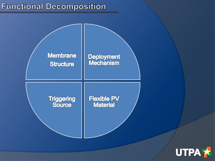
Functional Decomposition Membrane Structure Deployment Mechanism
This detailed analysis covers the functional decomposition of a deployment mechanism for a membrane structure, focusing on design constraints, concept variants, decision-making factors, and material selection. The sub-functions of deployment mechanism design, actuators/linkages, pressure-induced mechanisms, shape memory materials, and their relative scores are explored. Additionally, the membrane structure design constraints, material options like LDPE, Nylon-6, PET, and thin aluminum foil, along with their stiffness, strength, flexibility, and cost considerations are discussed.

Download Presentation

Please find below an Image/Link to download the presentation.
The content on the website is provided AS IS for your information and personal use only. It may not be sold, licensed, or shared on other websites without obtaining consent from the author.If you encounter any issues during the download, it is possible that the publisher has removed the file from their server.
You are allowed to download the files provided on this website for personal or commercial use, subject to the condition that they are used lawfully. All files are the property of their respective owners.
The content on the website is provided AS IS for your information and personal use only. It may not be sold, licensed, or shared on other websites without obtaining consent from the author.
E N D
Presentation Transcript
Functional Decomposition Membrane Structure Deployment Mechanism Triggering Source Flexible PV Material UTPA
Sub-Function l Deployment Mechanism Design Constraints: oWeight (DC1) oCost (DC2) oTime to Deploy (DC3) Concept Variants: oActuators/Linkages (CV1) oPressure Induced (CV2) oShape Memory Material (CV3) Weight Cost Time 2 Deploy Row Sum Nominal Score (DC1) (DC2) (DC3) (Rel. Weight) 0.389 x 4 3 7 Weight (DC1) 0.278 2 X 3 5 Cost (DC2) 0.333 3 3 x 6 Time2Deploy (DC3) 5 7 6 18 Col. Sum 1 UTPA
Sub-Function l Deployment Mechanism Actuators/ Linkages Pressure Induced Shape Memory Material Row sum Norm. Score Weight Actuators/Linkages X 2 1 3 0.167 Pressure Induced Shape Memory Material Col. Sum 0.444 4 X 4 8 5 2 X 7 0.389 9 4 5 18 1 Actuators/ Linkages Pressure Induced Shape Memory Material Row sum Norm. Score Cost Actuators/Linkages Pressure Induced Shape Memory Material Col. Sum X 5 1 X 1 5 2 10 0.111 0.556 5 1 X 6 0.333 10 2 6 18 1 Actuators/ Linkages Pressure Induced Shape Memory Material Row sum Norm. Score Time to Deploy Actuators/Linkages X 2 1 3 0.167 Pressure Induced Shape Memory Material Col. Sum 0.500 4 X 5 9 5 1 X 6 0.333 UTPA 9 3 6 18 1
Sub-Function l Selection Relative Score= Relative Score= Scv Selection Scvi i * *Wdc Wdci i i i=1,2,3, etc. =1,2,3, etc. Deployment Mechanism Decision Time to Deploy Weight Cost Score Actuators/Linkages 0.0567 0.0367 0.0567 0.15 Pressure Induced 0.50 0.1467 0.1867 0.1667 Shape Memory 0.13 0.11 0.11 0.35 Decision Pressure Induced Wins UTPA
Sub-Function lI Membrane Structure Design Constraints: oMembrane Stiffness - Strength oMembrane Flexibility oCost Concept Variants: oLDPE oNylon-6 oPET oThin Aluminum Foil Stiffness Membrane Cost Row Sum Normalized Strength Flexibility Score Stiffness x 2 3 5 0.278 Strength Membrane 4 x 3 7 0.389 Flexibility Cost 3 3 x 6 0.333 Colum Sum UTPA 7 5 6 18 1.00
Sub-Function lI Membrane Structure Thin Membrane Strength Row SumNormalized LDPE Nylon-6 PET Aluminum foil 1 2 3 Score LDPE Nylon-6 PET Thin Aluminum foil Colum Sum x 3 5 2 x 4 1 3 X 4 8 0.111 0.222 0.333 12 4 5 3 X 12 0.333 12 11 7 6 36 1 Thin Membrane Flexibility Normalized Score LDPE Nylon-6 PET Aluminum foil 5 5 5 Row Sum x 2 2 4 X 2 3 4 X 12 11 9 0.333 0.306 0.250 LDPE Nylon-6 PET Thin Aluminum foil 2 1 1 x 4 0.111 3 7 7 15 36 1 Colum Sum Thin Normalized Score Cost LDPE Nylon-6 PET Aluminum foil 2 4 4 Row Sum LDPE Nylon-6 PET x 1 4 2 x 5 2 2 x 6 7 13 0.167 0.194 0.361 Thin 5 3 2 x 10 0.278 UTPA Aluminum foil Colum Sum 10 10 6 10 36 1
Sub-Function lI Selection Membrane Decision Stiffness Flexibility Cost Score PET 0.111 0.083 0.120 0.314 Nylon-6 0.074 0.102 0.065 0.241 LDPE Thin Al Foil Decision 0.037 0.111 0.111 0.037 0.055 0.093 0.203 0.241 PET Wins UTPA
Sub-Function lll PV Material 1. Design Constraints: oFlexibility oCost oEfficiency Design Variants: 1. Organic Polymer 2. Amorphous Silicon 3. CIGS (Copper Indium Gallium Selenide) 2. 3. Flexibility x Cost 4 Efficiency 4 Row Sum 8 Nom. Score 0.444 0.278 Flexibility 2 x 3 5 Cost 2 3 x 5 0.278 Efficiency 4 7 7 18 1 Col. Sum UTPA
Sub-Function lll PV Material Concept Variant Rankings with Respect to Power Efficiency Power Efficiency amorphous Organic Polymer x Si: crystalline, amorphous CIGS, CZTS 5 Col. Sum 9 Organic Polymer Si: crystalline, CIGS, CZTS Row sum Norm. Score 2 1 3 0.167 4 x 3 7 0.389 3 5 x 4 8 0.444 1 18 Concept Variant Rankings with Respect to Cost Organic Polymer crystalline, amorphous Organic Polymer x Si: crystalline, amorphous CIGS, CZTS 1 Col. Sum 2 Si: CIGS, CZTS Row sum Norm. Score Cost 5 5 10 0.556 1 x 3 4 0.222 3 8 x 8 4 0.222 1 18 Concept Variant Rankings with Respect to Flexibility Organic Polymer crystalline, amorphous Organic Polymer x Si: crystalline, amorphous CIGS, CZTS 1 Col. Sum 2 Si: CIGS, CZTS Row sum Norm. Score Flexibility 5 5 10 0.556 1 x 4 5 0.278 2 7 x 9 3 0.167 1 18 UTPA
Sub-Function lII Selection PV Material Decision Efficiency Cost Flexibility Score Organic Polymer Si: crystalline, amorphous CIGS, CZTS 0.0556 0.1852 0.1852 0.4260 0.1296 0.0741 0.0926 0.2963 0.1481 0.0741 0.0556 0.2778 Organic Polymer Wins Decision UTPA
Sub-Function lV - Triggering Source 1. 2. Design Constraints: oWeight oCost oPower 3. Concept Variants: 1. Pump / Solenoid Switch 2. Magnets 3. Thermal Expansion Triggering Source Weight Cost Power Sum of Row Weight Score Weight Cost Power X 3 4 7 3 X 4 7 2 2 X 4 5 5 8 18 0.278 0.278 0.444 1 UTPA
Sub-Function lV - Triggering Source Weight Air Magnetic Thermal Air Magnetic Thermal Sum of Row Weight Score X 2 3 4 X 3 3 3 X 7 5 6 18 0.389 0.278 0.333 1 Cost Air Magnetic Thermal Air Magnetic Thermal Sum of Row Weight Score X 3 1 3 X 3 5 3 X 8 6 4 18 0.444 0.333 0.222 1 Power Air Magnetic Thermal Air Magnetic Thermal Sum of Row Weight Score X 2 2 4 X 3 4 3 X 8 5 5 18 0.444 0.278 0.278 1 UTPA
Sub-Function lV Selection Decision Weight Cost Power Score Air 0.130 0.148 0.148 0.426 Magnetic 0.093 0.111 0.093 0.297 Thermal 0.111 0.074 0.093 0.278 UTPA
Final Design Membrane Structure Deployment Mechanism Triggering Source Flexible PV Material UTPA