Fundamental Concepts of Soil Conductivity and Conduction Mechanisms
Soil is a complex system with solid, liquid, and gas components affecting its conductivity. Water content, state, and distance from solid particles influence the types of water in soil and its conductivity behavior. Factors such as porosity, electrolyte type, and temperature affect soil resistivity, with diffusion velocities of water molecules and ions being crucial in determining soil conductance.

Download Presentation

Please find below an Image/Link to download the presentation.
The content on the website is provided AS IS for your information and personal use only. It may not be sold, licensed, or shared on other websites without obtaining consent from the author.If you encounter any issues during the download, it is possible that the publisher has removed the file from their server.
You are allowed to download the files provided on this website for personal or commercial use, subject to the condition that they are used lawfully. All files are the property of their respective owners.
The content on the website is provided AS IS for your information and personal use only. It may not be sold, licensed, or shared on other websites without obtaining consent from the author.
E N D
Presentation Transcript
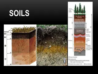
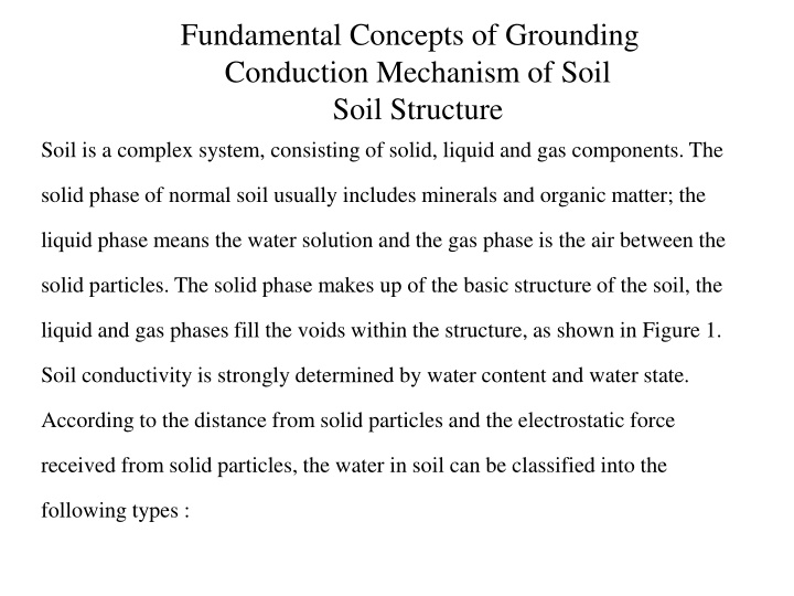
Fundamental Concepts of Grounding Conduction Mechanism of Soil Soil Structure Soil is a complex system, consisting of solid, liquid and gas components. The solid phase of normal soil usually includes minerals and organic matter; the liquid phase means the water solution and the gas phase is the air between the solid particles. The solid phase makes up of the basic structure of the soil, the liquid and gas phases fill the voids within the structure, as shown in Figure 1. Soil conductivity is strongly determined by water content and water state. According to the distance from solid particles and the electrostatic force received from solid particles, the water in soil can be classified into the following types :
Strongly Associated Water. Near the surface of soil particles, the water molecules cram together closely and cannot move freely due to the great intensity of the electrostatic field. This type of water is called strongly associated water. Weakly Associated Water. Being farther from the soil particles, the intensity of the electrostatic field has comparatively decreased, so the water molecules are more active and weakly oriented. This type of water is still mainly affected by the electrostatic field and is called weakly associated water. Capillary Water. As the distance between soil particles and water molecules increases, the water molecules become mainly affected by gravity. Although the electrostatic field still plays a role, it does not have a primary function. This type is called capillary water. Gravity Water. As the distance between soil particles and water molecules continues to increase, the effect of the electrostatic field becomes negligible to the water molecules, and the water molecules are only controlled by gravity
the resistivity of soil or rock normally depends on the degree of porosity and the type of electrolyte and the temperature. Metallic conduction, solid electrolytic conduction can occur but only when specific native metals and minerals are present . Because of the charges and ions attracted onto the surface of soil particles, soil can be considered as a polyvalent electrolyte. Soil conductance is the contribution of both charged soil particles (known as colloidal particle conductance, mainly decided by the amount of charge on the surface of soil particles) and ions in solution (known as ion conductance, mainly decided by the diffusion velocity of ions).
the diffusion velocity is affected by the resistance of the water molecules. As the temperature drops, the water becomes more viscous and its diffusion becomes slower because the resistance of water molecules increases. In contrast, the ions are affected by the soil electrostatic resistance. As the temperature lowers, the average kinetic energy of ions decreases and the capacity to overcome the soil electrostatic resistance also decreases and the diffusion velocity slows up. So, ion conductance decreases and soil resistivity increases as the temperature drops. When the soil temperature decreases to 0C or even lower, most of the water in the soil is frozen gradually and the ice (with high resistivity) fills the voids between the soil particles in the form of grains or laminas, so the conductive cross-section of soil reduces.
Finally, there would be only particle conductance created by the charges on the surface of soil particles, which is not related to temperature, so a saturation phenomenon appears. Figure 1 Photo showing the microstructure of soil.
Grounding is provided to connect some parts of electrical equipment and installations or the neutral point of a power system to the earth. This provides dispersing paths for fault currents and lightning currents in order to stabilize the potential and to act as a zero potential reference point to ensure the safe operation of the power system and electrical equipment and the safety of power system operators and other persons. Grounding is achieved by grounding devices (or ground devices) buried in soil.
The grounding devices of a power system can be divided into simple one for transmission line towers, such as a horizontal grounding electrode (or ground electrode), vertical ground rod, or ring grounding electrode, other is the grounding grid (or ground grid) for a substation or power plant.
The grounding device is a single metal conductor or a group of metal conductors buried in soil, including horizontally or vertically buried metal conductors (grid metal conductor ).
The grounding system refers to the whole system, including the grounding device of a substation or power plant, and all metal tanks for the power apparatus and electrical equipment, towers, overhead ground wires, neutral points of transformers and the metal sheaths of cables connected with the grounding device.
The basic parameter to indicate the electrical property of a grounding device is grounding resistance (or ground resistance), which is defined as the ratio of the voltage on the grounding device with respect to the zero potential point at infinity and the current injected into earth through the grounding device. If the current is a power-frequency alternating current (AC), the grounding resistance is called a power-frequency grounding resistance. If the current is an impulse current, such as a lightning current, then it is called an impulse grounding impedance.
Classification of Grounding The grounding devices of AC electrical equipment for a power system can be divided into three categories according to their functions: working grounding, lightning protection grounding and protective grounding.
Working Grounding Based on whether the neutral point is grounded, an AC power system can be classified into a neutral point effective grounding system or a neutral-point ineffective grounding system (including neutral-point ungrounded system, neutral-point resistance grounding system and neutral-point reactance grounding system).
In order to reduce the operating voltage on the insulation of the power apparatus, the neutral points of power systems of 110 kV and above are solidly grounded. For the neutral-point effectively grounded operation mode, under normal situations, the voltage on the insulation of the power apparatus (such as a power transformer) is the phase voltage. If the neutral-point is insulated, when the single-phase grounding fault occurs, the voltage on the insulation of the power apparatus is the line voltage before the breaker cuts off the fault, which is times as high as the phase voltage. The neutral-point effectively grounded operation mode can effectively reduce the voltage on the insulation of the power apparatus and the insulation level of the power apparatus is reduced, so the purpose of reducing the insulation size and lowering the cost of the equipment is achieved.
For the neutral-point solidly grounded system, the current through the grounding device is the unbalanced current of the system under normal situations and, when a short circuit fault occurs, a short-circuit current of tens of kilo-amperes (kA) will flow through the grounding device, and usually the short-circuit current will last about 0.5 s.
For a power distribution system, a step-down transformer is used to connect the high-voltage system with the low-voltage system and, according to whether the neutral point of the transformer is grounded, the low-voltage distribution system can be classified into a grounded system (either solidly or through impedance) or an ungrounded system. Figure 2 shows a low-voltage distribution system with neutral point grounded. If someone touches the low-voltage conductor, a loop will be formed in which the current through the body is related to the contact resistance between the body and earth. If the contact resistance is small, a dangerous current will flow through the body and harm it.
Figure 2 Solid grounding of a low-voltage distribution system.
shortcoming of an ungrounded system is that there is no way to inhibit this abnormal voltage and it will cause a hazard on the secondary side, when the system voltage is increased for some special reason, such as the mixed contact of the high and low voltage circuits, a lightning impulse.