Fundamental Hardware Requirements for Logic Design
Essential components of logic design, including communication methods, computation processes, and storage techniques. Learn about digital signals, computing with logic gates, combinational circuits, bit and word equality, and bit-level multiplexors. Discover how logic gates, Boolean functions, and Hardware Control Language (HCL) play crucial roles in computer architecture.

Download Presentation

Please find below an Image/Link to download the presentation.
The content on the website is provided AS IS for your information and personal use only. It may not be sold, licensed, or shared on other websites without obtaining consent from the author.If you encounter any issues during the download, it is possible that the publisher has removed the file from their server.
You are allowed to download the files provided on this website for personal or commercial use, subject to the condition that they are used lawfully. All files are the property of their respective owners.
The content on the website is provided AS IS for your information and personal use only. It may not be sold, licensed, or shared on other websites without obtaining consent from the author.
E N D
Presentation Transcript
Logic Design CSCI 370: Computer Architecture
Overview of Logic Design Fundamental Hardware Requirements Communication How to get values from one place to another Computation Storage Bits are Our Friends Everything expressed in terms of values 0 and 1 Communication Low or high voltage on wire Computation Compute Boolean functions Storage Store bits of information
Digital Signals 0 1 0 Voltage Time Use voltage thresholds to extract discrete values from continuous signal Simplest version: 1-bit signal Either high range (1) or low range (0) With guard range between them Not strongly affected by noise or low quality circuit elements Can make circuits simple, small, and fast
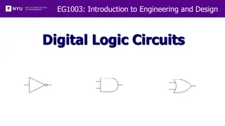
Computing with Logic Gates And Or Not a b a b a out out out out = a && b out = a || b out = !a Outputs are Boolean functions of inputs Respond continuously to changes in inputs With some, small delay Falling Delay Rising Delay a && b b Voltage a Time
Combinational Circuits Acyclic Network Primary Inputs Primary Outputs Acyclic Network of Logic Gates Continously responds to changes on primary inputs Primary outputs become (after some delay) Boolean functions of primary inputs
Bit Equality Bit equal a HCL Expression eq bool eq = (a&&b)||(!a&&!b) b Generate 1 if a and b are equal Hardware Control Language (HCL) Very simple hardware description language Boolean operations have syntax similar to C logical operations We ll use it to describe control logic for processors
Word Equality Word-Level Representation b63 eq63 B Eq Bit equal = a63 b62 A eq62 Bit equal a62 HCL Representation bool Eq = (A == B) Eq b1 eq1 Bit equal 64-bit word size HCL representation Equality operation Generates Boolean value a1 b0 eq0 Bit equal a0
Bit-Level Multiplexor s Bit MUX HCL Expression bool out = (s&&a)||(!s&&b) b out a Control signal s Data signals a and b Output a when s=1, b when s=0
Word Multiplexor Word-Level Representation s s B b63 Out MUX out63 A a63 HCL Representation int Out = [ s : A; 1 : B; ]; b62 out62 a62 Select input word A or B depending on control signal s HCL representation Case expression Series of test : value pairs Output value for first successful test out0 b0 a0
HCL Word-Level Examples Minimum of 3 Words Find minimum of three input words HCL case expression Final case guarantees match int Min3 = [ A < B && A < C : A; B < A && B < C : B; 1 : C; ]; C Min3 B MIN3 A 4-Way Multiplexor s1 s0 Select one of 4 inputs based on two control bits int Out4 = [ !s1&&!s0: D0; !s1 : D1; !s0 : D2; 1 : D3; ]; D0 D1 HCL case expression Out4 MUX4 D2 Simplify tests by assuming sequential matching D3
Arithmetic Logic Unit 0 1 2 3 Y Y Y Y A A A A A L U A L U A L U A L U X + Y X - Y X & Y X ^ Y X X X X B B B B OF ZF CF OF ZF CF OF ZF CF OF ZF CF Combinational logic Continuously responding to inputs Control signal selects function computed Corresponding to 4 arithmetic/logical operations in Y86-64 Also computes values for condition codes
Registers Structure i7 D C o7 Q+ i6 D C o6 Q+ i5 D C o5 Q+ i4 D C o4 Q+ I O i3 D C o3 Q+ i2 D C o2 Q+ i1 D C Clock o1 Q+ i0 D C o0 Q+ Clock Stores word of data Different from program registers seen in assembly code Collection of edge-triggered latches Loads input on rising edge of clock
Register Operation State = x State = y Rising clock Input = y Output = x Output = y x y Stores data bits For most of time acts as barrier between input and output As clock rises, loads input
State Machine Example Comb. Logic 0 Accumulator circuit Load or accumulate on each cycle A L U 0 Out MUX In 1 Load Clock Clock Load x0 x1 x2 x3 x4 x5 In x0 x0+x1 x0+x1+x2 x3 x3+x4 x3+x4+x5 Out
Random-Access Memory valA A srcA valW Register file W Read ports Write port dstW valB B srcB Stores multiple words of memory Address input specifies which word to read or write Register file Holds values of program registers %rax, %rsp, etc. Register identifier serves as address ID 15 (0xF) implies no read or write performed Multiple Ports Can read and/or write multiple words in one cycle Each has separate address and data input/output Clock
Register File Timing Reading Like combinational logic Output data generated based on input address After some delay Writing Like register Update only as clock rises valA x 2 A srcA Register file x valB B srcB 2 x 2 y 2 valW Rising clock y 2 Register file valW W Register file dstW W dstW Clock Clock
Hardware Control Language Very simple hardware description language Can only express limited aspects of hardware operation Parts we want to explore and modify Data Types bool: Boolean a, b, c, int: words A, B, C, Does not specify word size---bytes, 64-bit words, Statements bool a = bool-expr ; int A = int-expr ;
HCL Operations Classify by type of value returned Boolean Expressions Logic Operations a && b, a || b, !a Word Comparisons A == B, A != B, A < B, A <= B, A >= B, A > B Set Membership A in { B, C, D } Same as A == B || A == C || A == D Word Expressions Case expressions [ a : A; b : B; c : C ] Evaluate test expressions a, b, c, in sequence Return word expression A, B, C, for first successful test
Summary Computation Performed by combinational logic Computes Boolean functions Continuously reacts to input changes Storage Registers Hold single words Loaded as clock rises Random-access memories Hold multiple words Possible multiple read or write ports Read word when address input changes Write word as clock rises