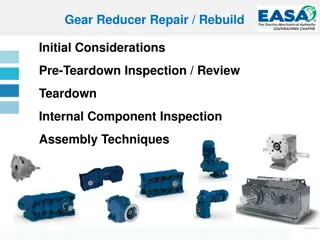
Gear Box Housing Design Parameters and Functions
The design of gear box housing involves determining various parameters such as wall thickness, bolt diameters, and safety distances to ensure proper functionality. Functions of the gear box housing include serving as a lubricant carrier, mounting bearings, fixation to the base, and oil level indication.

Download Presentation

Please find below an Image/Link to download the presentation.
The content on the website is provided AS IS for your information and personal use only. It may not be sold, licensed, or shared on other websites without obtaining consent from the author.If you encounter any issues during the download, it is possible that the publisher has removed the file from their server.
You are allowed to download the files provided on this website for personal or commercial use, subject to the condition that they are used lawfully. All files are the property of their respective owners.
The content on the website is provided AS IS for your information and personal use only. It may not be sold, licensed, or shared on other websites without obtaining consent from the author.
E N D
Presentation Transcript
Critical Design Review Wind Turbine with Gearbox Team G: Nick Koerner (Lead), Meteb Almutairi, Chris Batsch, Mike Villamar
Project Objectives The Main Goal is Control o The Arduino Mega Microcontroller will serve as the control center of the wind turbine. o Items that are being controlled by the microcontroller: Transistor Switching E-Brake Voltage Monitor Physical Hydraulic Brake Controlled by Servo Frequency Detection Simple Voltage regulator being used to protect microcontroller Efficiency and Power Output o High Efficiency is desired Switching Regulator o 5V, 2A, and 10W of Power
Modes of Operation Generation Mode o The E-brake switch will be open, and voltage monitor switch will be closed. o This allows for the generator to spin freely, and the battery bank to connect to the generator. Shutdown Mode o The E-Brake switch will be closed, and the voltage monitor switch will be open. o The generator will be shorted: Slows down the generator and dumps energy into the dump load. o The hydraulic brake will be activated by the servo, and cause the wind turbine to come to a complete stop. o Generation will be reactivated after a delay, or battery bank needs charging, or manual override.
Subassemblies Battery Bank Sub Specs: Batteries Lithium Ion Battery 2800mAh Battery Bank provides 9 V, 2.16 A Capacitor 1000 uF Generator Sub Specs: Bridge Rectifier IGBT Power Resistor Generator Frequency Detection Voltage Protection 1N4742 Zener Diode Max: 12 V, 1 W RS402L MAX: 100 V, 4 A ISL9V3040P3 MAX: 430 V, 17 A 50W ElectriFly Ammo
Subassemblies Brake Sub Specs: Turnigy Digital Metal Gear Servo 6 V Input Torque: 17 kg/cm Load Sub Specs: Step Down Switching Regulator (2 Options) L4978 IC Requires 8 V to 55 V input Produces 5 V and 2 A output ~90% Efficient Simple and all values given NR887D IC Requires 4.5 V to 18 V input Produces 5 V and 2 A output ~90% Efficient Not all values given, further testing once obtained Voltage Monitor (R6 & R7) Simple Voltage Divider for 5 V Analog Pin
Construction Plan Structural Hardware: o Much of the structural hardware used in the previous wind turbine project will be recycled in this current design, therefore the plan is to build on top of that. Previous components Used: o The Blades, Shaft, Gearbox, Generator, and Hydraulic Brake will be reused. Battery Bank o Brackets and metal tabs will be used to connect the batteries in the correct setup. The new components that are chosen will fit on the aluminum platform (shown on next slide). What does not fit, will rest a platform on the ground.
Additional Fabrication Plans Proto-Boards o The current plan is to use the EECS shop provided vector proto-boards to place the circuits upon. The Goal o To make custom PCB circuit boards using the EECS shop s PCB milling machine. o Depending on the time, and Eagle CAD training, the task can be completed before the deadline.
Testing DC Motor for in Lab Wind Simulations Wind Tunnel for Final Testing o The Max Wind Speed Tested is 34 MPH Tests the Generation and Shutdown Modes o >40 MPH Shutdown Feature o Can or will be Adjusted Input/Output Efficiency
In Lab Wind Simulation Data from Testing Wind Speed [MPH] Voltage [V] RPM of Generator [RPM] Frequency [Hz] 11.18 1.79 1005.82 16.76 22.37 3.46 2012.53 33.54 33.55 4.50 3018.35 50.31
Schedule Task Projected Completion Proposal DC Motor for Wind Simulation Preliminary Research Analyze Wind Turbine Design PDR Detailed Overview Research Circuit Schematic CDR Order Parts Programming Microcontroller Construction Wind Tunnel Testing Project Completion 2/4/2015 2/13/2015 2/20/2015 2/20/2015 2/20/2015 3/13/2015 3/13/2015 4/1/2015 4/3/2015 4/17/2015 4/17/2015 4/24/2015 5/6/2015
Challenges/Risks Programming Programming the microcontroller will take some time and research. Scheduling Meeting times due to different schedules of everyone in group is a conflict. Batteries Potential risk of explosion and or fire. Components Size, rating, and cost must be considered for durability and because structure from last year is being used. Testing Availability of wind tunnel and making sure wind simulation matches actual wind tunnel performance.