General Class Radio Signals & Equipment Overview
In this informational resource, delve into the realm of General Class Radio signals and equipment, focusing on Superheterodyne Receivers. Explore how these receivers work, from signal conversion to audio output. Learn about RF amplifiers, mixers, detectors, and more that make up a Superheterodyne Receiver, essential for passing your General Class exam.

Download Presentation

Please find below an Image/Link to download the presentation.
The content on the website is provided AS IS for your information and personal use only. It may not be sold, licensed, or shared on other websites without obtaining consent from the author.If you encounter any issues during the download, it is possible that the publisher has removed the file from their server.
You are allowed to download the files provided on this website for personal or commercial use, subject to the condition that they are used lawfully. All files are the property of their respective owners.
The content on the website is provided AS IS for your information and personal use only. It may not be sold, licensed, or shared on other websites without obtaining consent from the author.
E N D
Presentation Transcript
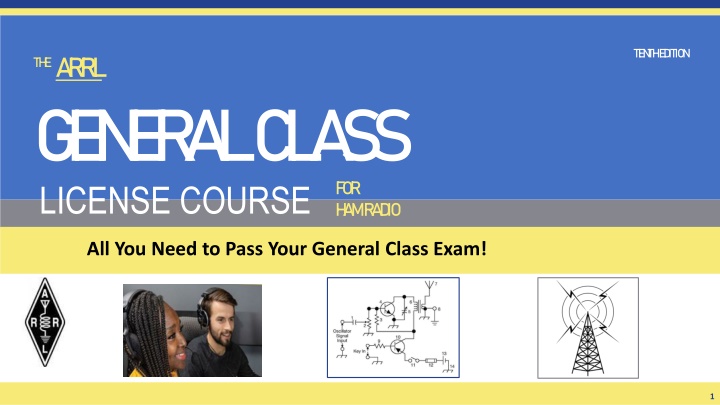
TE N TH E D ITION TH EA RRL G E N E R A L C L A SS LICENSE COURSE FOR H A M R A D IO All You Need to Pass Your General Class Exam! 1
Resource & Reference www.arrl.org/shop/Licensing-Education-and-Training 2
Chapter 5 Part 2 of 2 ARRL General Class Radio Signals & Equipment Sections 5.4, 5.5 Receivers, HF Station Installation 3
Section 5.4 Superheterodyne Receivers Most receivers used by today s amateurs are superheterodyne Received signals are incredibly weak on the order of nano or picowatts Received signals are first strengthened by the RF amplifier, then applied to the RF input of a mixer The local oscillator (LO) is adjusted so that the desired signal creates a mixing product at the intermediate frequency (IF) A detector or demodulator stage follows the IF to recover the modulating information Input amplifier gain, demodulator stage bandwidth, and input amplifier noise can all affect receiver sensitivity 4
Fig. 5.16 A superheterodyne receiver converts signals to audio in two steps. The front end converts the frequency of a signal to the intermediate frequency (IF) where most of the gain of the receiver is provided. A second mixer the product detector converts the signal to audio frequencies. 5
Superheterodyne Receivers (cont.) Once amplified to a more usable level, SSB and CW signals are demodulated by a product detector, a special type of mixer If an AM signal is being received, a product detector or envelope detector recovers the modulating signal Output of the detector is an audio signal amplified by an audio frequency (AF) amplifier and input to a speaker, headphones, or sound card 6
Superheterodyne Receivers (cont.) The RF amplifier and mixer are the receiver s front end Processes weak signals at their original frequencies A preselector is often used to reject out-of-band signals A preamplifier (preamp) is used if additional sensitivity is needed (weak signals) 7
Superheterodyne Receivers (cont.) The simplest possible superhet consists of a mixer connected to the antenna, an oscillator to act as the LO, and a detector that operates directly on the resultingIF signal See Figure 5.16 The single-frequency IF stages make it much easier to create high quality filters and high gain amplifiers without having to be tuned. Only the LO needs to be tuned in a superhet receiver. Recall the formula for intermodulation (mixing of signals) f1 + f2 For example, to convert an RF signal on 14.250 MHz to an IF of 455 kHz, the LO must be tuned to either 14.250 455 kHz = 13.795 MHz or to 14.250 + 455 kHz = 14.705 MHz 8
Superhets (cont.) Superhets have some weaknesses, like all radio designs Because there are mixing products at both the sum and difference frequencies, undesired signals can create their own mixing products at the IF see next slide for examples (refer to Fig 5.4, explained in Chapter 5 Part 1) Fig 5.4 9
Superhet (cont.) Another flaw is caused by the LO and other oscillator circuits. Leakage of signals into the signal path can cause steady signals to appear (called birdies). Fig. 5.16 shows a single-conversion, with only one mixer converting the signal from RF to IF The IF stages provide most of the gain and selectivity Filtering is applied at each IF (allows filter bandwidth selection for desired signal) this gives the best received signal quality with the lowest unwanted noise and interference, maximizing the signal-to-noise ratio (SNR) 10
Superhet Mixer Weakness Example (see Fig 5.4) In a mixer, with an RF Input or Input Frequency (f1) and Local Oscillator (f2), remember there are mixing products at f1 f2 meaning f1 + f2 AND f1 f2 With a LO = 13.800 MHz, a mixing product of 455 kHz (0.455 can be generated by a signal of either 14.255 MHz or 13.345 MHz). 14.255 MHz (signal) 13.800 MHz (LO) = 0.455 MHz 13.800 MHz (LO) 13.345 MHz (signal) = 0.455 MHz Assuming that the INTENDED signal at 14.255 MHz is an image response. 11
FM Receivers (see Fig. 5.17) Similar to AM/SSB/CW superhets The linear IF amplifier is replaced by a limiter Limiter amplifies the received signal until all amplitude modulated info (noise) is removed and only a square wave of the varying frequency remains Audio information is recovered by a discriminator or quadrature detector that replaces the product detector 12
Fig 5.17: Once the FM signal is converted to the IF, hi-gain amplifiers called limiters change the signal to a square wave that only varies in frequency (not amplitude). A discriminator converts the frequency variations to audio. 13
Digital Signal Processing (DSP) The general term for converting signals from analog to digital is digital signal processing Fig 5.18 (below): DSP systems use an analog-to-digital converter (ADC) to change the signal to digital data. A special type of microprocessor then performs the mathematical operations on the data to accomplish filtering, noise reduction, or other functions. A digital-to-analog converter (DAC) changes the processed data back to analog form for output as audio. 14
Digital Signal Processing (cont.) Two advantages over analog circuitry Performance & flexibility DSP offers selectable preprogrammed filters and allow the operator to adjust the filter bandwidth and shape and even to define new filters Expensive functions in analog circuits can be implemented in DSP as a program without additional hardware 15
Managing Receiver Gain (RF Gain) When looking for weak signals, set RF gain to maximum (for highest receiver sensitivity) Lower RF gain volume to reduce background noise Automatic gain control (AGC) circuits vary gain of the RF and IF amplifiers so output volume stays constant for both weak and strong signals AGC circuit changes the voltage that controls the IF amp gain. This voltage is read by the S-meter (measures signal strength). 16
RF Gain and AGC (cont.) S-meters are calibrated in S-units One S-unit equals up to 6 dB (fourfold = 4X) change in signal strength S-9 (a strong signal) is located at the midpoint of the display Larger values to the right (20, 40, 60) These correspond to dB above S-9 Reading of S-9 + 20 dB is a signal 20 dB (100 times) stronger than an S-9 signal 17
Receiver Linearity If the received signal is distorted, spurious signals will appear just as if a transmitting station were emitting them The most common form of receiver nonlinearity is overload (also called front-end overload) or gain compression Solution to overload is to filter out the offending signal or reduce receiver gain (attenuator circuit). Proper use of attenuator and RF gain controls can dramatically reduce received noise distortion caused by strong signals. 18
Rejecting Interference and Noise IFfilters narrow the receiver s passband (removes unwanted signals) Notch filters remove signals in a very narrow band of frequencies (such as a signal tone from an interfering carrier) Passband or IFshift adjust receiver s passband above or below the displayed carrier frequency (avoids interference on adjacent frequencies) Reverse sideband controls allow switching between receiving CW signals above carrier frequency (USB) and below it (LSB). Avoids interference by placing the signals on the other side of the carrier where filtering rejects them. 19
Rejecting Interference and Noise (cont.) Noise blankers sense short, sharp pulses in the IF signals and reduce the gain of the IF and audio amplifiers during the pulse called blanking Adjustable noise blankers can be set to blank the receiver at different noise levels Noise reduction is performed by the DSP Removes hiss and noise from the audio that is not part of the desired speech, data, or CW Increasing the noise reduction level may cause some of the desired signal to be removed (causes distortion) use the least noise reduction require to minimize this 20
What is the purpose of the notch filter found on many HF transceivers? A. To restrict the transmitter voice bandwidth B. To reduce interference from carriers in the receiver passband C. To eliminate receiver interference from impulse noise sources D. To remove interfering splatter generated by signals on adjacent frequencies G4A01 (B) Page 5-21 22
What is one advantage of selecting the opposite, or reverse, sideband when receiving CW? A. Interference from impulse noise will be eliminated B. More stations can be accommodated within a given signal passband C. It may be possible to reduce or eliminate interference from other signals D. Accidental out-of-band operation can be prevented G4A02 (C) Page 5-21 23
How does a noise blanker work? A. By temporarily increasing received bandwidth B. By redirecting noise pulses into a filter capacitor C. By reducing receiver gain during a noise pulse D. By clipping noise peaks G4A03 (C) Page 5-21 24
What happens as a receivers noise reduction control level is increased? A. Received signals may become distorted B. Received frequency may become unstable C. CW signals may become severely attenuated D. Received frequency may shift several kHz G4A07 (A) Page 5-21 25
What is the purpose of using a receive attenuator? A. To prevent receiver overload from strong incoming signals B. To reduce the transmitter power when driving a linear amplifier C. To reduce power consumption when operating from batteries D. To reduce excessive audio level on strong signals G4A13 (A) Page 5-20 26
What does an S meter measure? A. Carrier suppression B. Impedance C. Received signal strength D. Transmitter power output G4D04 (C) Page 5-20 27
How does a signal that reads 20 dB over S9 compare to one that reads S9 on a receiver, assuming a properly calibrated S meter? A. It is 10 times less powerful B. It is 20 times less powerful C. It is 20 times more powerful D. It is 100 times more powerful G4D05 (D) Page 5-20 28
How much change in signal strength is typically represented by one S unit? A. 6 dB B. 12 dB C. 15 dB D. 18 dB G4D06 (A) Page 5-20 29
How much must the power output of a transmitter be raised to change the S meter reading on a distant receiver from S8 to S9? A. Approximately 1.5 times B. Approximately 2 times C. Approximately 4 times D. Approximately 8 times G4D07 (C) Page 5-20 30
How is a product detector used? A. Used in test gear to detect spurious mixing products B. Used in transmitter to perform frequency multiplication C. Used in an FM receiver to filter out unwanted sidebands D. Used in a single sideband receiver to extract the modulated signal G7C04 (D) Page 5-18 31
Which of the following is an advantage of a digital signal processing (DSP) filter compared to an analog filter? A. A wide range of filter bandwidths and shapes can be created B. Fewer digital components are required C. Mixing products are greatly reduced D. The DSP filter is much more effective at VHF frequencies G7C06 (A) Page 5-19 32
Which parameter affects receiver sensitivity? A. Input amplifier gain B. Demodulator stage bandwidth C. Input amplifier noise figure D. All these choices are correct G7C08 (D) Page 5-18 33
Which mixer input is varied or tuned to convert signals of different frequencies to an intermediate frequency (IF)? A. Image frequency B. Local oscillator C. RF input D. Beat frequency oscillator G8B01 (B) Page 5-17 34
What is the term for interference from a signal at twice the IF frequency from the desired signal? A. Quadrature response B. Image response C. Mixer interference D. Intermediate interference G8B02 (B) Page 5-18 35
Why is it good to match receiver bandwidth to the bandwidth of the operating mode? A. It is required by FCC rules B. It minimizes power consumption in the receiver C. It improves impedance matching of the antenna D. It results in the best signal-to-noise ratio G8B09 (D) Page 5-19 36
Section 5.5 HF Station Installation HF operating, with longer wavelengths and higher field strengths, makes grounding and interference control much more important The General Exam focuses on three related areas Mobile installations RF grounding RF interference 37
Mobile Installations Power Connections Mobile radios that can output 100 W require solid power connections capable of supplying 20 A or more Solid state radios perform unpredictably with input voltage drops below the specified minimum power supply voltage Best power connection is direct to battery, heavy gauge wire, with both leads fused Do NOT use cigarette lighter or aux socket usually rated for only a few amperes insufficient to supply a 100 W HF radio* * If you have an older vehicle something from the 1980 s, for example it may have an old-fashioned cigarette lighter socket rated with enough amps to power your radio. But, confirm with BOTH owner s manuals before you try it. Every machine, operated WRONGLY enough, becomes a SMOKE machine! 38
Mobile Installations Antenna Connections A limitation of mobile installations is that electrically short (smaller in terms of wavelength) antennas are less efficient that full-sized ones Particularly true on lower frequency bands Tips to improve antenna performance Use most efficient antenna you can Make sure your ground connections to vehicle are solid Mount antenna where it is clear of metal surfaces 39
Mobile Interference Different interference sources than home stations Ignition noise (spark plugs firing) n/a in diesel engines Alternator whine Vehicle s accessories On-board control computers Electric motors in fuel pumps, windows, and battery charging systems Winch motors in 4X4 vehicles & trucks 40
Grounding & Bonding AC grounding prevents hazardous voltages from appearing on equipment chassis, creating a shock hazard To manage RF, bond equipment enclosures together (see Fig 5.19) Bonding means to connect two points together to minimize voltage differences between them During digital operation, unwanted RF currents can cause distortion, erratic operation of computer interfaces, activate transmitter improperly, and garble digital protocols 41
Figure 5.19 This example of a typical RF bonding bus at the operating position helps keep all of the equipment at the same RF voltage. 42
Grounding & Bonding (cont.) Bonding basics Connect all metal equipment enclosures directly together or to a common RF bonding bus Keep connections, straps, and wires SHORT Use short, heavy conductors (#12 or #14 AWG) or strap If strong RF is present, use a piece of wide flashing or screen under the equipment, connected to the bonding bus If ground connection is resonant at an odd number of wavelengths, it will generate high impedance (enables RF voltages on enclosures and cables) 43
Grounding & Bonding (cont.) Ground loops are created by a continuous current path around a series of equipment connections Loop acts as a single-turn inductor picks up voltages from magnetic fields (from transformers, ac wiring, etc.) Result is a hum in transmitted signals or that interferes with control or data signals Ground loops can be avoided by connecting all ground conductors to the RF bonding bus 44
RF Interference (RFI): Causes & Solutions RFI CAUSE SOLUTION Fundamental Overload Radio/TV receivers unable to reject strong signals causes distortion or inability to receive desired signal Prevent signal by using filters in signal path Common-mode & Direct pickup From electronic equipment with internal electronics picked up on outside of cable shields and conductors of unshielded connections Block current with RF chokes Harmonics Spurious emissions from an amateur station may be received by radio or TV equipment (there is no 1stharmonic it s called the fundamental frequency) Use a low-pass filter at the transmitter Intermodulation Poor contacts between conductors picking up RF signals can create a nonlinear connection that acts as a mixer and mixing products from the signals Find/repair the poor contact or block the RF signals (look for odd-order harmonics closest to the original frequencies) Arcing A spark or sustained arc creates radio crackling or buzz over wide frequency range, (from power-line hardware) May require power company to make repairs; filter specific equip. 45
Common RFI Symptoms RFI is quite varied Some more common types are CW, FM, or data: Interference consists of ON/OFF buzzes, humming, clicks or thumps when the interfering signal is transmitted AM phone: Equipment experiencing overload or direct detection will often emit a replica of the speaker s voice SSB voice: Similar to AM phone, but voice will be distorted or garbled 46
Suppressing RFI Filters are effective and easy to install Block RF by placing an impedance in its path Form conductor carrying RF current into an RF choke by winding it around or through a ferrite core Ferrite beads placed on cables to prevent RF common-mode from flowing on outside of cables/shields Interference to audio equipment and sensor connections can be eliminated by using a small (100 pF to 1 nF) bypass capacitor across balanced connections 47
Which of the following might be useful in reducing RF interference to audio frequency devices? A. Bypass inductor B. Bypass capacitor C. Forward-biased diode D. Reverse-biased diode G4C01 (B) Page 5-25 49
Which of the following could be a cause of interference covering a wide range of frequencies? A. Not using a balun or line isolator to feed balanced antennas B. Lack of rectification of the transmitter s signal in power conductors C. Arcing at a poor electrical connection D. Using a balun to feed an unbalanced antenna G4C02 (C) Page 5-25 50


")
")
")
")
")
")
")

")
")
")
")


")


")
")
: Causes & Solutions")