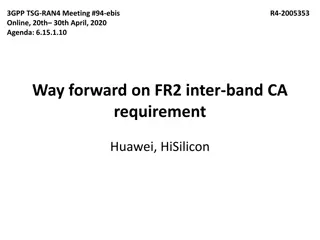
General & PDSCH Demodulation Requirements for Inter-Cell Interference
Explore the Way Forward regarding general and PDSCH demodulation requirements for inter-cell interference in 3GPP TSG-RAN-WG4 Meeting #99-e. The agenda includes specifications for MMSE-IRC, common test parameters, network types, SSB configurations, and target PDSCH parameters for scenario 1.
Download Presentation

Please find below an Image/Link to download the presentation.
The content on the website is provided AS IS for your information and personal use only. It may not be sold, licensed, or shared on other websites without obtaining consent from the author. If you encounter any issues during the download, it is possible that the publisher has removed the file from their server.
You are allowed to download the files provided on this website for personal or commercial use, subject to the condition that they are used lawfully. All files are the property of their respective owners.
The content on the website is provided AS IS for your information and personal use only. It may not be sold, licensed, or shared on other websites without obtaining consent from the author.
E N D
Presentation Transcript
3GPP TSG-RAN WG4 Meeting #99-e E-meeting, 19 27 May 2021 Agenda Item: 9.11.2.1 R4-2108664 Way Forward on general and PDSCH demodulation requirements for inter- cell interference MMSE-IRC Intel Corporation,
Common test parameters Background: RAN4 meeting #98-bis-e agreements Physical cell ID of 0 for the serving cell, and cell ID i for interferer i (where i 1, maximum number of i is FFS) SCS: FDD 15kHz, TDD 30kHz (Same SCS is used for the target and the interference cells) TDD DL/UL configuration for 30kHz SCS: 7D1S2U(S=6D+4G+4U) Number of carriers: In Rel-17, MMSE-IRC receiver performance requirements with interference cell condition is defined only for single carrier scenario PDCCH and PDSCH allocation in time domain Use symbols #0 and #1 of each slot for PDCCH PDSCH mapping type A, Start symbol 2, Duration 12 PDSCH allocation in frequency domain: Full PRB DMRS configuration For both serving and interfering cells, DMRS Type 1 with single symbol front loaded and 1 additional DMRS, with FDM applied between DMRS and data (number of CDM groups without data is equal to 1), i.e., overlapped DMRS between target and interferer Antenna configuration 2 Tx as baseline for serving cell and interfering cells UE with 2 and 4 RX ULA low correlation as baseline 2
Common test parameters Network type FFS whether to consider asynchronized for FDD Channel bandwidth Use 10MHz for FDD 15kHz and 40MHz for TDD 30kHz for initial simulation purpose FFS whether to consider 40 MHz for FDD 15kHz and 100 MHz for TDD 30kHz for requirements definition SSB configuration Option 1: All SSBs (serving cell and interference cell(s)) are in the same time/frequency resources Option 2: Serving cell SSB and interference cell(s) SSB(s) are in the different time/frequency resources TRS/CSI-RS configuration TRS/CSI-RS colliding with TRS/CSI-RS interference Propagation condition Consider TDLA30-10 and TDLC300-100 channel models for evaluation purpose and select only one for requirements definition 3
Target PDSCH parameters for scenario 1 Background: RAN4 meeting #98-bis-e agreements Transmission rank: Use rank 1 as baseline PRB bundle size: Set PRB bundle size as 2 for target PDSCH HARQ process number: 4 for FDD 15kHz SCS and 8 for TDD 30kHz SCS as baseline RAN4 meeting #99-e agreements MCS Use MCS 4 (QPSK, CR=0.3) and MCS 13 (16QAM, CR=0.5) for initial simulation purpose Further discuss MCS for requirements definition Consider MCS corresponding to QPSK and 16QAM modulation formats Precoding model Random precoder with Type I SP codebook Performance measurement point Option 1: SINR at 70% TP Option 2: SNR at 70% TP 4
Interference model for scenario 1 Background: RAN4 meeting #98-bis-e agreements Transmission rank of interfering PDSCH Use the following assumptions initial simulation purpose: random rank with 70% and 30% probability for rank 1 and rank 2 transmission in the interfering cell(s) Precoding of interfering PDSCH Random precoding with single panel type I codebook per slot and per PRB bundling granularity, with PRB bundling size of 2. Modulation order of interfering PDSCH Use 16QAM randomly modulated symbols for initial simulation assumption and other options not precluded. 5
Interference model for scenario 1 Deployment for initial simulations Consider Homogeneous deployment assumptions FFS whether for consider HetNet deployment assumptions DIP values for Homogeneous deployment assumptions for initial simulations Consider DIP1/2 = -1.73/-8.66 dB (INR1/2 = 5.43/-1.50 dB in case of 2 interference cells and INR 3.1 dB in case of 1 interference cell) as baseline for initial link level analysis for Synchronous network Results for another interference profiles are welcome Other options are not precluded for requirements definition FFS assumptions for asynchronous network INR values for HetNet deployment assumptions for initial simulations (in case HetNet is agreed) Option 1: INRs 11.39 and 5.45 dB or DIPs -1.23 and -7.16 dB Other options are not precluded Number of explicitly modeled interference cells Further discuss whether to consider explicit modelling of 1 or 2 interference cells Analysis of NR interference profile System level analysis from interested companies is not precluded Methodology for interference profile configuration Option 1: Use the DIP methodology Option 2: Use INR methodology 6
Release independence RAN4 discuss whether the UE demodulation with inter-cell interference is released independent from Rel-15 or not, after RAN4 agree with the detailed simulation assumption 7


