Genesis of Austin Flint Murmur Mechanisms and Theories
The genesis of Austin Flint murmur involves a complex interplay of ventricular filling patterns, jet impacts on valves, and turbulent flows. Various theories propose different mechanisms contributing to the distinctive murmur components. Austin Flint's original description in 1862 laid the foundation for understanding this unique cardiac phenomenon.

Download Presentation

Please find below an Image/Link to download the presentation.
The content on the website is provided AS IS for your information and personal use only. It may not be sold, licensed, or shared on other websites without obtaining consent from the author.If you encounter any issues during the download, it is possible that the publisher has removed the file from their server.
You are allowed to download the files provided on this website for personal or commercial use, subject to the condition that they are used lawfully. All files are the property of their respective owners.
The content on the website is provided AS IS for your information and personal use only. It may not be sold, licensed, or shared on other websites without obtaining consent from the author.
E N D
Presentation Transcript
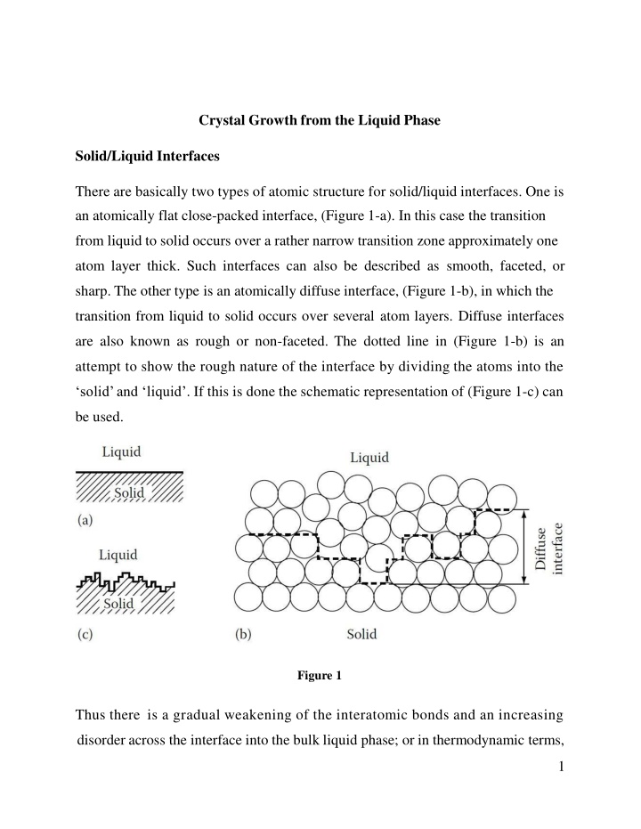
Crystal Growth from the Liquid Phase Solid/Liquid Interfaces There are basically two types of atomic structure for solid/liquid interfaces. One is an atomically flat close-packed interface, (Figure 1-a). In this case the transition from liquid to solid occurs over a rather narrow transition zone approximately one atom layer thick. Such interfaces can also be described as smooth, faceted, or sharp. The other type is an atomically diffuse interface, (Figure 1-b), in which the transition from liquid to solid occurs over several atom layers. Diffuse interfaces are also known as rough or non-faceted. The dotted line in (Figure 1-b) is an attempt to show the rough nature of the interface by dividing the atoms into the solid and liquid . If this is done the schematic representation of (Figure 1-c) can be used. Figure 1 Thus there is a gradual weakening of the interatomic bonds and an increasing disorder across the interface into the bulk liquid phase; or in thermodynamic terms, 1
enthalpy and entropy gradually change from bulk solid to bulk liquid values across the interface as shown in (Figure 2). When the solid and liquid are in equilibrium (at Tm) the high enthalpy of the liquid is balanced by high entropy so that both phases have the same free energy. In the interface, however, the balance is Solid-Liquid. disturbed thereby giving rise to an excess free energy, Figure 2 The type of structure chosen by a particular system will be that which minimizes the interfacial free energy. According to a simple theory developed by Jackson: the optimum atomic arrangement depends mainly on the latent heat of fusion (Lf) relative to the melting temperature (Tm). This theory predicts that there is a critical value of (Lf/Tm 4R) above which the interface should be flat and below which it should be diffuse. Most metals have Lf/Tm R and are therefore predicted to have rough interfaces, (R = 8.314 J/mole. K). On the other hand some intermetallic compounds and elements such as Si, Ge, Sb as well as most non-metals have high 2
values of (Lf /Tm) and generally have flat closepacked interfaces. If the model is applied to solid/vapour interfaces LS (the heat of sublimation) should be used instead of Lf and then flat surfaces are predicted even for metals, in agreement with observations. An atomically rough or diffuse interface associated with metallic systems, and an atomically flat or sharply defined interface often associated with non-metals. Because of the differences in atomic structure these two types of interface migrate in quite different ways. Rough interfaces migrate by a continuous growth process while flat interfaces migrate by a lateral growth process involving ledges. Continuous Growth The solidification of metals is usually a diffusion controlled process. For pure metals growth occurs at a rate controlled by heat conduction (diffusion) whereas alloy solidification is controlled by solute diffusion. In diffuse interfaces, it can be assumed that atoms can be received at any site on the solid surface. For this reason it is known as continuous growth. Such a mode of growth is reasonable because the interface is disordered and atoms arriving at random positions on the solid will not significantly disrupt the equilibrium configuration of the interface. The situation is, however, more complex when the equilibrium interface structure is atomically smooth as in the case of many non- metals. 3
Lateral Growth Materials with high entropy of melting prefer to form atomically smooth, close- packed interfaces. For this type of interface the minimum free energy also corresponds to the minimum internal energy. If a single atom leaves the liquid and attaches itself to the flat solid surface, (Figure 3-a), it can be seen that the interfacial energy will increase with increasing of interfaces. There is therefore little probability of the atom remaining attached to the solid and it is likely to jump back into the liquid. If the interface contains ledges, (Figure 3-b), liquid atoms will be able to join the ledges with a much lower resulting increase in interfacial energy. If the ledge contains a jog, J, atoms from the liquid can join the solid without any increase in the interfacial energy. Consequently the probability of an atom remaining attached to the solid at these positions is much greater than for an atom joining a facet. Smooth solid/liquid interfaces can therefore be expected to advance by the lateral growth of ledges. Figure 3 Heat Flow and Interface Stability: In pure metals solidification is controlled by the rate at which the latent heat of solidification can be conducted away from the solid/liquid interface. Conduction can take place either through the solid or the liquid depending on the temperature 4
gradients at the interface. Consider for example solid growing at a velocity (v) with a planar interface into a superheated liquid (Figure 4-a). The heat flow away from the interface through the solid must balance that from the liquid plus the latent heat generated at the interface, i.e. Where K is the thermal conductivity, is the temperature gradient (dT/dx), the subscripts S and L stand for solid and liquid, v is the rate of growth of the solid, and Lf is the latent heat of fusion per unit volume. When a solid grows into a superheated liquid, a planar solid/liquid interface is stable. This can be shown as follows. Suppose that as a result of a local increase in v a small protrusion forms at the interface, (Figure 4-c). Therefore the temperature gradient in the liquid ahead of the nodule will increase while that in the solid decreases. Consequently more heat will be conducted into the protruding solid and less away so that the growth rate will decrease below that of the planar regions and the protrusion will disappear. Figure 4 5
The situation is, however, different for a solid growing into supercooled liquid, Figure 5. If a protrusion forms on the solid in this case the negative temperature gradient in the liquid becomes even more negative. Therefore heat is removed more effectively from the tip of the protrusion than from the surrounding regions allowing it to grow preferentially. A solid/liquid interface advancing into supercooled liquid is thus inherently unstable. Figure 5 Heat conduction through the solid as depicted in Figure 4, arises when solidification takes place from mould walls which are cooler than the melt. Heat flow into the liquid, however, can only arise if the liquid is supercooled below Tm. Such a situation can arise at the beginning of solidification if nucleation occurs at impurity particles in the bulk of the liquid. Since a certain supercooling is required before nucleation can occur, the first solid particles will grow into supercooled liquid and the latent heat of solidification will be conducted away into the liquid. An originally spherical solid particle will therefore develop arms in many 6
directions as shown in Figure 6. As the primary arms elongate their surfaces will also become unstable and break up into secondary and even tertiary arms. This shape of solid is known as a dendrite. Dendrite comes from the Greek for tree. Dendrites in pure metals are usually called thermal dendrites to distinguish them from dendrites in alloys. It is found experimentally that the dendrite arms are always in certain crystallographic directions: e.g. 100 in cubic metals, and 1100 in hcp metals. Figure 6 7
Figure 7 At the tip of a growing dendrite the situation is different from that of a planar interface because heat can be conducted away from the tip in three dimensions. We assume the solid is isothermal ( ), the (negative) temperature gradient is approximately given by ( Tc / r) where Tc is the difference between the interface temperature (Ti) and the temperature of the supercooled liquid far from the dendrite (T ) as shown in Figure 8, so Thus for a given Tcrapid growth will be favoured by small values of r due to the increasing effectiveness of heat conduction as r diminishes.As a result of the Gibbs Thomson effect equilibrium across a curved interface occurs at an undercooling Trbelow Tmgiven by 8
The minimum possible radius of curvature of the tip is when Tr equals the total undercooling T0 = Tm T . This is just the critical nucleus radius r* given by . Therefore in general Tr is given by ( T0 r*/r). Finally since T0 = Tc + Tr , so It can thus be seen that the tip velocity tends to zero as r r* and as r . The maximum velocity is obtained when r = 2r*. Growth Directions in Various Crystal Structures: FCC <100> BCC <100> HCP <10-10> BCT (tin) <110> In cubic crystals the <100> dendrite arm growth direction leads to the secondary arms being perpendicular to the primary arms. Also, the tertiary arms are perpendicular to the secondary arms. The movement of a boundary separating liquid from solid, under the influence of a temperature gradient normal to the boundary, is the result of two different atomic movements. Atoms leave the liquid and join the solid = rate of attachment Atoms leave the solid and join the liquid = rate of detachment 9
Planes of looser atomic packing can better accommodate an atom that leaves the liquid. Where a growing crystal will assume faces that represent slow growing planes. The shape of a growing crystal can be affected by the fact that different crystal faces have different growth rates. Close-packed low-energy faces tend to grow growing slower and, as a result, they are the ones that are mostly present in a crystallite. Figure 8 10
Figure 9 Total rate of a phase transformation induced by cooling is a product of the nucleation rate (driving force increases with undercooling but diffusion needed for atomic rearrangement slows down with T decrease) and growth rate (diffusion controlled - slows down with T decrease) Figure 10. At high T (close to Tm): low nucleation and high growth rates coarse microstructure with large grains. At low T (strong undercooling): high nucleation and low growth rates fine structure with small grains. 11
Figure 10 12
Grains Structure of Ingots and Castings Most engineering alloys begin by casting process. If the as-cast pieces are permitted to retain their shape afterwards, or are reshaped by machining, they are called castings. If they are later to be worked, e.g. by rolling, extrusion or forging, the pieces are called ingots. In either case the principles of solidification are the same. Generally speaking three different zones can be distinguished in solidified alloy ingots (Figure 11). These zones are (i) chill zone of equiaxed crystals, columnar zone of elongated grains, and (iii) a central equiaxed zone. (ii) a Figure 11 Chill Zone: During pouring the liquid in contact with the cold mould wall is rapidly cooled below the liquidus temperature. Many solid nuclei then form on the mould wall and begin to grow into the liquid, (Figure 12). As the mould wall warms up it is possible for many of these solidified crystals to break away from the wall under the 13
influence of the turbulent melt. If the pouring temperature is low the whole of the liquid will be rapidly cooled below the liquidus temperature and the crystals swept into the melt may be able to continue to grow. This is known as big-bang nucleation since the liquid is immediately filled with a myriad of crystals. This produces an entirely equiaxed ingot structure, i.e. no columnar zone forms, this also can be done by adding seeds or inoculants which are a solid small particles added to molten metal in the mold. If the pouring temperature is high, on the other hand, the liquid in the centre of the ingot will remain above the liquidus temperature for a long time and consequently the majority of crystals soon remelt after breaking away from the mould wall. Only those crystals remaining close to the wall will be able to grow to form the chill zone. Figure 12 Columnar Zone Very soon after pouring the temperature gradient at the mould walls decreases and the crystals in the chill zone grow dendritically in certain crystallographic directions, e.g. <100> in the case of cubic metals. Those crystals with a <100> 14
direction close to the direction of heat flow, i.e. perpendicular to the mould walls, grow fastest and are able to outgrow less favourably oriented neighbours (Figure 13). This leads to the formation of the columnar grains all with <100> almost parallel to the column axis. Note that each columnar crystal may contain primary dendrite arms (if it is an alloy).As the diameter of these grains increases additional primary dendrite arms appear by a mechanism in which some tertiary arms grow ahead of their neighbours as shown in the figure. Figure 13 Equiaxed Zone The equiaxed zone consists of equiaxed grains randomly oriented in the centre of the ingot.An important origin of these grains is thought to be melted-off dendrite side-arms. It can be seen that the side arms are narrowest at their roots. Therefore, if the temperature around the dendrite increases after it has formed, it will begin to melt and may become detached from the main stem. Provided the temperature falls again before the arm completely disappears it can then act as a seed for a new dendrite. An effective source of suitable temperature pulses is provided by the 15
turbulent convection currents in the liquid brought about by the temperature differences across the remaining melt. Convection currents also provide a means of carrying the melted-off arms away to where they can develop uninhibited into equiaxed dendrites. If convection is reduced, fewer seed crystals are created causing a larger final grain size and a greater preponderance of columnar grains. Shrinkage Effects Most metals shrink on solidification and this has important consequences for the final ingot structure. In pure metals, and also in narrow freezing range alloys (where the mushy zone is also narrow); as the outer shell of solid thickens the level of the remaining liquid continually decreases until finally when solidification is complete the ingot contains a deep central cavity or pipe. In alloys with a wide freezing range the mushy zone can occupy the whole of the ingot. In this case no central pipe is formed. Instead the liquid level gradually falls across the width of the ingot as liquid flows down to compensate for the shrinkage of the dendrites. However, as the inter-dendritic channels close up, this liquid flow is inhibited so that the last pools of liquid to solidify leave small voids or porosities. 16
Segregation in Ingots and Castings Two types of segregation can be distinguished in solidified structures. There is macrosegregation, i.e. composition changes over distances comparable to the size of the specimen, and there is microsegregation that occurs on the scale of the secondary dendrite arm spacing. There are four important factors that can lead to macrosegregation in ingots. These are: (i) shrinkage due to solidification and thermal contraction; (ii) density differences in the inter-dendritic liquid; (iii) density differences between the solid and liquid; and (iv) convection currents driven by temperature-induced density differences in the liquid. All of these factors can induce macrosegregation by causing mass flow over large distances during solidification. Shrinkage effects can give rise to what is known as inverse segregation. As the columnar dendrites thicken solute-rich liquid [assuming (partitioning constant) k < 1] must flow back between the dendrites to compensate for shrinkage and this raises the solute content of the outer parts of the ingot relative to the centre. The effect is particularly marked in alloys with a wide freezing range, e.g. Al Cu and Cu Sn alloys. Interdendritic liquid flow can also be induced by gravity effects. For example during the solidification of Al Cu alloys the copper rejected into the liquid raises its density and causes it to sink. The effect can be reinforced by convection currents driven by temperature differences in the ingot. Gravity effects can also be observed when equiaxed crystals are forming. The solid is usually denser than the liquid and sinks carrying with it less solute than the bulk composition (assuming k < 1). This can, therefore, lead to a region of negative segregation near the bottom of the ingot. 17
The combination of all the above effects can lead to complex patterns of macrosegregation. Figure 14 for example illustrates the segregation patterns found in large steel ingots. In general segregation is undesirable as it has marked deleterious effects on mechanical properties. The effects of microsegregation can be mitigated by subsequent homogenization heat treatment, but diffusion in the solid is far too slow to be able to remove macrosegregation which can only be combated by good control of the solidification process. Figure 14 18


 and generally have flat closepacked")


![❤[PDF]⚡ Escaping from Eden: Does Genesis Teach that the Human Race was Created](/thumb/21697/pdf-escaping-from-eden-does-genesis-teach-that-the-human-race-was-created.jpg)