GPS Navigation State-Space Models
This content delves into GPS navigation utilizing state-space models. It covers various scenarios such as Allan standard deviations of receiver clock time measurement error, GPS-aided 9-state INS with clock error models, differential carrier phase for positioning, and more. Explore the intricacies and applications of GPS technology in aerospace engineering.
Download Presentation

Please find below an Image/Link to download the presentation.
The content on the website is provided AS IS for your information and personal use only. It may not be sold, licensed, or shared on other websites without obtaining consent from the author.If you encounter any issues during the download, it is possible that the publisher has removed the file from their server.
You are allowed to download the files provided on this website for personal or commercial use, subject to the condition that they are used lawfully. All files are the property of their respective owners.
The content on the website is provided AS IS for your information and personal use only. It may not be sold, licensed, or shared on other websites without obtaining consent from the author.
E N D
Presentation Transcript
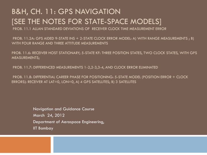
B&H, CH. 11: GPS NAVIGATION [SEE THE NOTES FOR STATE-SPACE MODELS] PROB. 11.1 ALLAN STANDARD DEVIATIONS OF RECEIVER CLOCK TIME MEASUREMENT ERROR PROB. 11.2A: GPS AIDED 9-STATE INS + 2-STATE CLOCK ERROR MODEL: A) WITH RANGE MEASUREMENTS ; B) WITH FOUR RANGE AND THREE ATTITUDE MEASUREMENTS PROB. 11.6: RECEIVER HOST STATIONARY; 5-STATE KF: THREE POSITION STATES, TWO CLOCK STATES, WITH GPS MEASUREMENTS; PROB. 11.7: DIFFERENCED MEASUREMENTS 1-2,2-3,3-4, AND CLOCK ERROR ELIMINATED PROB. 11.8: DIFFERENTIAL CAREER PHASE FOR POSITIONING: 5-STATE MODEL (POSITION ERROR + CLOCK ERRORS): RECEIVER AT LAT=0, LON=0, A) 4 GPS SATELLITES; B) 3 SATELLITES Navigation and Guidance Course March 24, 2012 Department of Aerospace Engineering, IIT Bombay
Prob. 11.1 Allan Standard Deviations of Receiver Clock Time Measurement Error: Exact, and its Approximations from its Two-State Model Allan Variance0.5 and its approximations: Time Measurement Error: 1 (s) 10-8 Allan Allan approx Allan mod (h0/(2 ))0.5 2h-1 (2/3 2 h-2 )0.5 0.5 10-9 10-10 10-2 10-1 100 101 102 103 GPS Measurement Interval (s)
Prob. 11.2a: GPS aided 9-state INS + 2-state clock error model: a) with range measurements: Input Parameters Earth's angular speed: omegaE = 0.7292115e-4 rad/s [east: 0; north: omegaE*cos(lambda); up: omegaE*sin(lambda)]; lambda=latitude Power Spectral Density of a poor quality accelerometer : S_acc = 0.0036 (m/s^2)^2/Hz ; it introduces spurious acceleration 0.06 (m/s^2)/Hz^0.5 = 0.06/9.81 Vehicle with modest dynamics: ENU Geographic frame rate: [-lamda_dot; (omegaE+phi_dot)*cos(lamda); (omegaE+phi_dot)*sin(lamda)] = 0.0061 g/Hz^0.5 = 6100 micro g/Hz^0.5 Power Spectral Density of a high quality gyro: Sgyro = 2.35e-11 (rad/s)^2/Hz; It introduces spurious drift rate omegax=-.0000157 rad/s; omegay=.0000727 rad/s; 2.35e-11 ^ 0.5 = 4.85e-6 (rad/s)/Hz^0.5 = Identical accelerometers and gyros for three axes 2.78e-4 (deg/s)/Hz^0.5 :
Prob. 11.2a: GPS aided 9-state INS + 2-state clock error model: a) with pseudorange measurements ( =15 m) (1/4) Prob. 11.2a: GPS ranging aided-INS (1 Hz GPS Measurements) 10-1 North Tilt East tilt Azimuth Error Tilt about North and East Axis and azimuth error (rad) 10-2 10-3 10-4 0 100 200 300 400 500 600 700 800 900 1000 time (s)
GPS aided 9-state INS + 2-state clock error model: a) with pseudorange measurements ( =15 m) (2/4) Prob. 11.2a: GPS ranging aided-INS (1 Hz GPS Measurements) 102 rms east rms north rms altitude rms east, north, altitude position error (m) 101 100 0 100 200 300 400 500 600 700 800 900 1000 time (s)
GPS aided 9-state INS + 2-state clock error model: a) with pseudorange measurements ( =15 m) (3/4) Prob. 11.2a: GPS ranging aided-INS (1 Hz GPS Measurements) 101 rms east rms north rms vertical rms east, north, vertical vel error (m/s) 100 10-1 0 100 200 300 400 500 600 700 800 900 1000 time (s)
GPS aided 9-state INS + 2-state clock error model: a) with pseudorange measurements ( =15 m) (4/4) rms range bias error due to receiver clock (m) rms range rate error due to receiver clock (m/s) Prob. 11.2a: GPS ranging aided-INS (1 Hz GPS Measurements) 102 101 100 0 100 200 300 400 500 600 700 800 900 1000 time (s) Prob. 11.2a: GPS ranging aided-INS (1 Hz GPS Measurements) 102 101 100 10-1 0 100 200 300 400 500 600 700 800 900 1000 time (s)
Prob. 11.2b: GPS aided 9-state INS + 2-state clock error model: b) with four range and three attitude measurements; compare with case a) Prob. 11.2b: GPS clock and attitude measurements aiding 9-state INS 10-1 North Tilt Azimuth Error Tilt about North Axis and azimuth error (rad) 10-2 10-3 10-4 0 100 200 300 400 500 600 700 800 900 1000 time (s)
10-1 North Tilt Azimuth Error Tilt about North Axis and azimuth error (rad) 10-2 b) With GPS range and attitude measurements: a multiantenna system 10-3 10-1 North Tilt Azimuth Error Tilt about North Axis and azimuth error (rad) 10-4 0 100 200 300 400 500 600 700 800 900 1000 time (s) 10-2 a) With GPS range measurements 10-3 10-4 0 100 200 300 400 500 600 700 800 900 1000 time (s) Brown and Hwang, Prob. 11.2: Integrated GPS/INS: 9-state INS + clock bias and rate model
Prob. 11.6: Receiver Host stationary; 5-state KF: three position states, two clock states, with GPS measurements; Q matrix % PSD of velocity white noise the integral of which is the position error in x, y, z % 5-state transition matrix: [x y z c*deltaT(range error) c*deltaTdot(range rate error)]' PHI=eye(state_dim); PHI(4,5)=dt; Sp=1.0; (m/s)^2/Hz % PSD of white noise inputs for two-state clock error % Measurement matrix (constant) H=[-0.3523 -0.0495 0.9346 1 0; 0.6199 0.7406 0.2593 1 0; -0.9506 -0.2553 0.1764 1 0; 0.9613 0.2129 0.1747 1 0]; % Measurement noise 1 sigma: 15 m, for 4 satellites GPS_sig = 15.0; % range measurement error, 1 sigma R = GPS_sig^2 *eye(4); Sf=0.4E-18*c^2 sec*(m/s)^2 Sg=1.58E-18*c^2 (1/sec)*(m/s)^2 Q=[Sp*dt 0 0 0 0; 0 Sp*dt 0 0 0; 0 0 Sp*dt 0 0; 0 0 0 Sf*dt+(Sg*dt^3)/3 (Sg*dt^2)/2; 0 0 0 (Sg*dt^2)/2 Sg*dt];
Prob. 11.6 Stationary host; Covariance Analysis of 5-state Position + clock error model with GPS measurements (1/2) 5-state Position + clock error Model, with GPS range measurements 35 x y z GPS 30 RMS Position error: x, y, z (m) 25 20 15 10 5 0 0 10 20 30 40 50 60 time (s)
Prob. 11.6 Stationary host; Covariance Analysis of 5-state Position + clock error model with GPS measurements (2/2) 5-state Position + clock error Model, with GPS range measurements 15 RMS clock range (m) range error Q(4,4)0.5 10 5 0 0 10 20 30 40 50 60 time (s) RMS clock range rate error (m/s) 102 range rate error Q(5,5)0.5 101 100 10-1 0 10 20 30 40 50 60 time (s)
Prob. 11.7: Differenced measurements 1-2,2-3,3-4, and clock error eliminated; position error sigma slightly greater than that with earlier 4 measurements (Prob. 11-6) Prob. 11.7: differencing meas. 1-2,2-3,3-4 to eliminate clock error 20 differenced and regular measurements: rms pos. error (m) differenced regular 18 16 14 12 10 8 6 4 2 0 0 20 40 60 80 100 120 140 160 180 200 Time(s)
Prob. 11.8a: Differential Career Phase for Positioning: 5-state model (position error + clock): receiver at Lat=0, Lon=0, 4 GPS satellites (1/2) Position error PSD % Error covariance matrix: 100 m; clock errors: 300 m range bias, 30 m/s range rate Sp=0.01; % m^2; How are the units consistent? Clock error sources: white noise PSDs Sf=0.4E-18*c^2 sec*(m/s)^2 Sg=1.58E-18*c^2 (1/sec)*(m/s)^2 PMINUS = [10000 0 0 0 0; % (100 m)^2 0 10000 0 0 0; 0 0 10000 0 0; 0 0 0 90000 0; % (300 m)^2 range bias equivalent to clock time bias Q=[Sp*dt 0 0 0 0; 0 Sp*dt 0 0 0; 0 0 Sp*dt 0 0; 0 0 0 0 900]; % (30 m/s)^2 range rate clock drift 0 0 0 Sf*dt+(Sg*dt^3)/3 (Sg*dt^2)/2; 0 0 0 (Sg*dt^2)/2 Sg*dt]; measurement noise: (0.005 m)^2 R=0.005^2 *eye(4);
Prob. 11.8a: Differential Career Phase for Positioning: 5-state model (position error + clock): receiver at Lat=0, Lon=0, 4 GPS satellites (1/2) Prob. 11.8a: 5-state model (position + clock) of Differential Carrier Phase Meas. 102 x (1 ) y (1 ) z (1 ) 101 x,y,z position change 1 (m) 100 10-1 10-2 0 100 200 300 400 500 600 700 800 900 1000 Time(s)
Prob. 11.8a: Differential Career Phase for Positioning: 5-state model (position error + clock): 4 satellites (2/2) Prob. 11.8a: Differential Carrier Phase Meas. 102 clock bias: range range rate RMS clock errors: range (m) and range rate (m/s) (1 ) 101 100 10-1 10-2 10-3 -100 0 100 200 300 400 Time(s) 500 600 700 800 900 1000
Prob. 11.8b: Differential Career Phase for Positioning: 5-state model (position error + clock): 3 satellites (1/2) Prob. 11.8a: 5-state model (position + clock) of Differential Carrier Phase Meas. 102 x (1 ) y (1 ) z (1 ) 101 x,y,z position change 1 (m) 100 Prob. 11.8: 5-state model (position + clock) of Differential Carrier Phase Meas. 102 10-1 x,y,z position change 1 (m) 101 x (1 ) y (1 ) z (1 ) 10-2 0 100 200 300 400 500 600 700 800 900 1000 100 Time(s) 10-1 10-2 0 200 400 600 800 1000 Time(s)
Prob. 11.8b: Differential Career Phase for Positioning: 5-state model (position error + clock): 3 satellites (2/2) Prob. 11.8a: Differential Carrier Phase Meas. 102 clock bias: range range rate RMS clock errors: range (m) and range rate (m/s) (1 ) 101 100 Prob. 11.8: Differential Carrier Phase Meas. 102 RMS clock errors: range (m) and range rate (m/s); 1 10-1 clock bias: range range rate 101 10-2 100 10-3 -100 0 100 200 300 400 Time(s) 500 600 700 800 900 1000 10-1 10-2 10-3 0 200 400 600 800 1000 Time(s)
