Handling CRS Interference in LTE and NR Scenarios
Discussing challenges and solutions for CRS interference in scenarios with overlapping spectrum for LTE and NR networks, focusing on scenarios, performance comparison, baseline schemes, and synchronization considerations.
Download Presentation

Please find below an Image/Link to download the presentation.
The content on the website is provided AS IS for your information and personal use only. It may not be sold, licensed, or shared on other websites without obtaining consent from the author. If you encounter any issues during the download, it is possible that the publisher has removed the file from their server.
You are allowed to download the files provided on this website for personal or commercial use, subject to the condition that they are used lawfully. All files are the property of their respective owners.
The content on the website is provided AS IS for your information and personal use only. It may not be sold, licensed, or shared on other websites without obtaining consent from the author.
E N D
Presentation Transcript
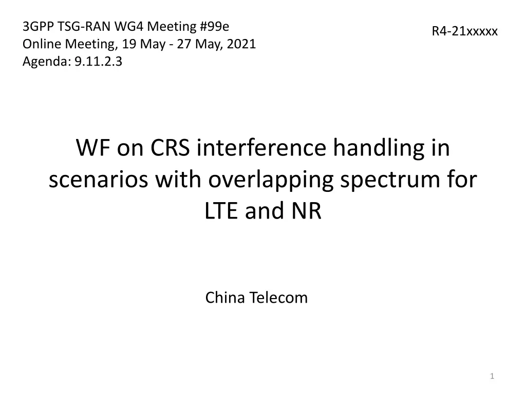
3GPP TSG-RAN WG4 Meeting #99e Online Meeting, 19 May - 27 May, 2021 Agenda: 9.11.2.3 R4-21xxxxx WF on CRS interference handling in scenarios with overlapping spectrum for LTE and NR China Telecom 1
General issues Scenarios According to WID, both scenarios are valid. Scenario 1: LTE and NR DSS Scenario 2: NR and LTE deployed in neighbouring BS/areas Scenario 1 and scenario 2 will be included for initial LLS evaluation: Scenario 1 with 15kHz Scenario 2 with 15kHz 30 kHz for scenario 2 can be deprioritized before RAN#93e 3
General issues Baseline RM scheme for performance comparison with PDSCH CRS-IM For scenario 1 with LTE and NR DSS: Rel-15 serving cell CRS-RM Rel-16 CRS-RM for 1 interference cell Case A: the 1 interference cell with RM is always the first dominant interference, i.e., INR1 Case B: the 1 interference cell with RM is NOT always the first dominant interference. e.g., INR of the 1 interference cell with RM is INR1 or INR2 with 50%: 50% probability. If the INR for the interference cell with RM is INR1, then the INR for the other interference cell is INR2, and vice versa. The INR levels for the two interference cells can be changed per [1000] slots. Case B is for initial simulation only, and FFS whether to consider it for performance requirement definition. Rel-15 RB symbol level RM for 2 interference cells For scenario 2 No RM Rel-15 CRS-RM for 1 interference cell Case A: the 1 interference cell with RM is always the first dominant interference, i.e., INR1 Case B: the 1 interference cell with RM is NOT always the first dominant interference e.g., INR of the 1 interference cell with RM is INR 1 or INR2 with 50%: 50% probability. If the INR for the interference cell with RM is INR1, then the INR for the other interference cell is INR2, and vice versa. The INR levels for the two interference cells can be changed per [1000] slots. Case B is for initial simulation only, and FFS whether to consider it for performance requirement definition. Rel-16 CRS-RM for 2 interference cells Companies are encouraged to bring analysis on the performance impact on LTE cell due to Rel- 16 RM 4
General issues Sync or async scenario for FDD Focus on Sync network before RP #93 meeting CBW and SCS for target and interference cells Use the following SCS/CBW for performance evaluation before RP #93e, FFS for performance requirement definition: FDD 15kHz: 10MHz CBW TDD 15kHz: to be discussed in the next meeting TDD 30kHz: to be discussed after RAN#93e in the next meeting PDCCH CRS-IM FFS whether to define neighboring cell LTE CRS-IM requirement for PDCCH 5
Reference receiver Reference receiver Assume neighbouring cell CRS-IM is used together with MMSE-IRC Assumption on CRS-IM Both CRS-IC and LLR weighting for the initial performance evaluation FFS for performance requirements definition. FFS NW assistant information existed or not, companies are encouraged to bring analysis with different options. Number of CRS cells to be mitigated It s up to UE implementation: 1 or 2 cell can be mitigated. UE processing time Encourage further analysis on UE processing time in RAN4 #100e for CRS-IC and LLR deweighting respectively. FFT processing Single FFT processing for sync and async scenarios. Further discuss for async scenarios after RAN#93e. 7
Interference model Number of interfering cells modelled in the simulation 2 interference cell will be modelled for initial LLS evaluation FFS for the configuration of requirements if introduced in later phase with the consideration together with the availability of NW assistant signalling. Interference power modeling Reuse the interference power modeling for LTE CRS-IM receiver, i.e., INR-i (signal level of the i-th dominant interference over Noc) methodology Interference power level Use option 1 with INR1 = 10.45 dB and INR2 = 4.6 dB as baseline, other power levels can also be simulated by interested companies. 9
Interference model CRS pattern Non-colliding between the serving cell CRS (if exits) and interference cell CRS Non-colliding CRS between the two interfering cells if there are two interference cells For example: For scenario 1, v-shift = 0, 1, 2 for the serving and two interference cells For scenario 2, v-shift = 1, 2 for the two interference cells PDSCH loading level on interference cell In time domain, probability of occurrence of data transmission in interference cells: simulate 20%, and it is also encouraged to simulate 0%, 50% and 100%. In frequency domain: full bandwidth allocation. 10
Interference model Time offset and frequency shift for sync network Option 1 for initial simulation: Time offset: The serving cell is 3 us and -1 us for interfering cell 1 and cell 2 respectively Frequency shift: The serving cell is 300 Hz and -100 Hz for interfering cell 1 and cell 2 respectively. Other options are not precluded. Transmission rank Reuse the assumption from LTE HomNet CRS-IM, i.e., 80% and 20% probability for rank 1 and rank 2 transmission in the interfering cell(s). NR PDSCH or LTE PDSCH transmission in interfering cells LTE PDSCH 11
Interference model Modulation scheme for the interference PDSCH Reuse the assumption from LTE HomNet CRS-IM, i.e., 16 QAM randomly modulated symbols in the interfering PDSCH when exists Precoding scheme for the interference PDSCH Random precoding MBSFN configuration for the interference LTE cell No MBSFN is configured on LTE carrier Center frequency for the interference LTE cell Same between serving cell and neighbouring cells 12
Target NR PDSCH parameters Rank for target NR PDSCH Rank 1 MCS for target NR PDSCH Cover QPSK MCS 4 and 16QAM MCS 13 for initial simulation FFS whether to cover 64QAM MCS 19 Precoding model for target NR PDSCH Random precoding (Single panel Type 1) with PRB bundling size is 2 with PRB bundling type is static HARQ process number for target NR PDSCH 4 for FDD, further discuss for TDD PDSCH mapping type and DMRS configuration for target NR PDSCH PDSCH mapping type A with full PRB allocation, use DMRS Type 1 with single symbol front loaded and 1 additional DMRS, with FDM applied between DMRS and data. 14
Target NR PDSCH parameters ZP CSI-RS, NZP CSI-RS and TRS configuration for target cell Reuse the Rel-15 assumptions for ZP CSI-RS, NZP CSI-RS and TRS configuration in PDSCH demodulation requirements for the serving cell SSB position for target cell Configure the first SSB in slot #0 in every 20 ms, and the slot #0 in every 20 ms is not scheduled for PDSCH transmission Start symbol (S) and symbol length (L) for the target PDSCH For the scenario that Rel-15 or Rel-16 CRS-RM is configured (for scenario 1 and 2): Focus on S = 3, L = 9. Interested companies can bring analysis for S = 3, L = 11. For the scenario that CRS-RM is not configured (for scenario 2): S = 2, L = 12 15
Target NR PDSCH parameters Overhead for TBS determination for the target PDSCH For the scenario that Rel-15 or Rel-16 CRS-RM is configured (for scenario 1 and 2): 18 For the scenario that CRS-RM is not configured (for scenario 2): 0 Target PDSCH performance measurement point Companies to provide simulation curves as well as the CRS-IM gain in terms of both SNR/SINR improvement and relative throughput improvement. Use SNR in the simulation. 16
Common parameters for target and interfering cells 17
Common parameters for target and interfering cells NR Carrier number Focus on NR single carrier scenario Tx antenna and LTE CRS port number For initial simulation, prioritize 4 CRS ports and interested companies can provide results for 2 CRS ports case. FFS for performance requirement definition. Rx antenna number 2Rx and 4Rx Propagation condition TDLA30-10 and ULA low for the initial simulation 18
Others 19
Other aspects for RAN4 #100e Discuss if there is any potential impact to other WGs. Collection of simulation results before RAN4 #100e Simulation results will be collected and calibrated in RAN4 draft reflector from Aug 2nd to 5th. Interested companies are encouraged to provide simulation results before the meeting if possible. Template for simulation result collection is provided in R4-2108663. 20
Thanks! 21

