Hazen Williams Equation for Pipe Flow Analysis
Learn about the Hazen Williams equation for pipe flow analysis, including how to calculate head loss in parallel and series pipes. Explore examples and practice problems to deepen your understanding of hydraulic principles.

Download Presentation

Please find below an Image/Link to download the presentation.
The content on the website is provided AS IS for your information and personal use only. It may not be sold, licensed, or shared on other websites without obtaining consent from the author. If you encounter any issues during the download, it is possible that the publisher has removed the file from their server.
You are allowed to download the files provided on this website for personal or commercial use, subject to the condition that they are used lawfully. All files are the property of their respective owners.
The content on the website is provided AS IS for your information and personal use only. It may not be sold, licensed, or shared on other websites without obtaining consent from the author.
E N D
Presentation Transcript
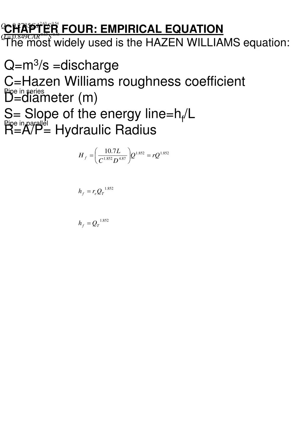
= . 2 63 . 0 54 2785 . 0 CHAPTER FOUR: EMPIRICAL EQUATION The most widely used is the HAZEN WILLIAMS equation: Q Cd S = . 0 63 . 0 45 . 0 849 Q CAR S Q=m3/s =discharge C=Hazen Williams roughness coefficient D=diameter (m) S= Slope of the energy line=hf/L R=A/P= Hydraulic Radius Pipe in series Pipe in parallel 10 7 . L = = . 1 852 . 1 852 Hf Q rQ . 1 852 . 4 87 C D . 1 852 h = r Q f e T . 1 852 h = Q f T
EXAMPLE Two parallel pipes each 150m long, one 200mm diameter and the other 150mm diameter, each with C=120 and QT=0.14m3/s, determine the head loss in meter of water. Two pipe in series one 30m long with a 300mm diameter and the second 100m long with a 250mm diameter each having a C=110, QT=0.14m3/s, determine the head loss in meter of water. SOLUTION: Pipe in parallel (a) 10 7 . L = = . 1 852 . 1 852 Hf Q rQ . 1 852 . 4 87 C D but r1=579.4, r2=2341.9
. 0 54 . 0 54 . 0 54 1 1 1 = + = . 0 0473 579 4 . 2351 9 . r e . 1 852 1 = = 284 54 . r e 0473 . 0 852 !. = = . 7 49 h r Q m f e T NOTE: n 1 = r e / 1 n 1 r = . 1 = 852 n . 1 852 h r Q (b) Pipe in series f e T = + = + = 18 = . 8961 153 . 05 171 . 95 r r r 1 2 e . 1 852 = 5 . 4 h r Q m f e T TAKE HOME ASSIGNMENT (1) The dimensions of the figure shown below are shown in this table, Find the total discharge in reservoir B. Pipe L(m) D(m) C r 1 2 3 75 100 150 0.05 0.07 0.1 110 110 100 2.91x10⁵ 5.39x10⁴ 2.37x10⁴