Hierarchical vs. Relational Database Management Systems: A Comprehensive Overview
Explore the fundamental concepts of databases, including Hierarchical and Relational Database Management Systems. Understand the role of a Database Management System (DBMS) in storing and retrieving data efficiently. Delve into the history and evolution of DBMS, from its inception by Charles Bachman to modern-day applications integrating XML. Gain insights into creating and structuring databases through practical examples. Discover the significance of DBMS in various domains and its impact on information management.

Download Presentation

Please find below an Image/Link to download the presentation.
The content on the website is provided AS IS for your information and personal use only. It may not be sold, licensed, or shared on other websites without obtaining consent from the author. If you encounter any issues during the download, it is possible that the publisher has removed the file from their server.
You are allowed to download the files provided on this website for personal or commercial use, subject to the condition that they are used lawfully. All files are the property of their respective owners.
The content on the website is provided AS IS for your information and personal use only. It may not be sold, licensed, or shared on other websites without obtaining consent from the author.
E N D
Presentation Transcript
DEPARTMENT oF COMPUTER SCIENCE St. Joseph s College (Autonomous) Tiruchirappalli - 2 The Hierarchical Approach Data Base Systems II B.SC CS 17UCS330207 Course Title Course Title Programme Programme Course Code Course Code Rev. Dr. S. Arul Oli SJ Assistant Professor
Relational Data Base Relational Data Base Management System Management System Rev. Rev. Dr. Dr. S. Arul Oli SJ S. Arul Oli SJ
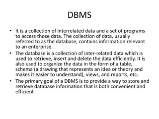
What is a Database? A database is a collection of related data which represents some aspect of the real world. A database system is designed to be built and populated with data for a certain task. What is DBMS? Database Management System (DBMS) is a software for storing and retrieving users' data while considering appropriate security measures. It consists of a group of programs which manipulate the database. The DBMS accepts the request for data from an application and instructs the operating system to provide the specific data. In large systems, a DBMS helps users and other third-party software to store and retrieve data. DBMS allows users to create their own databases as per their requirement. The term DBMS includes the user of the database and other application programs. It provides an interface between the data and the software application.
Example of a DBMS Example of a university database. This database is maintaining information concerning students, courses, and grades in a university environment. The database is organized as five files: The STUDENT file stores data of each student The COURSE file stores contain data on each course. The SECTION stores the information about sections in a particular course. The GRADE file stores the grades which students receive in the various sections The TUTOR file contains information about each professor. To define a database system: We need to specify the structure of the records of each file by defining the different types of data elements to be stored in each record. We can also use a coding scheme to represent the values of a data item. Basically, your Database will have 5 tables with a foreign key defined amongst the various tables 4
History of DBMS Here, are the important landmarks from the history: 1960 - Charles Bachman designed first DBMS system 1970 - Codd introduced IBM'S Information Management System (IMS) 1976- Peter Chen coined and defined the Entity-relationship model also know as the ER model 1980 - Relational Model becomes a widely accepted database component 1985- Object-oriented DBMS develops. 1990s- Incorporation of object-orientation in relational DBMS. 1991- Microsoft ships MS access, a personal DBMS and that displaces all other personal DBMS products. 1995: First Internet database applications 1997: XML applied to database processing. Many vendors begin to integrate XML into DBMS products. 5
Characteristics of Database Management System Provides security and removes redundancy Self-describing nature of a database system Insulation between programs and data abstraction Support of multiple views of the data Sharing of data and multiuser transaction processing DBMS allows entities and relations among them to form tables. It follows the ACID concept (Atomicity, Consistency, Isolation, and Durability). DBMS supports multi-user environment that allows users to access and manipulate data in parallel. 6
DBMS Flat File Management System Multi-user access It does not support multi-user access Design to fulfill the need for small and large businesses It is only limited to smaller DBMS system. Remove redundancy and Integrity Redundancy and Integrity issues Expensive. But in the long term Total Cost of Ownership is cheap It's cheaper Easy to implement complicated transactions No support for complicated transactions 7
Users in a DBMS Users in a DBMS environment Component Name environment Task Application Programmers The Application programmers write programs in various programming languages to interact with databases. Database Administrators Database Admin is responsible for managing the entire DBMS system. He/She is called Database admin or DBA. End-Users The end users are the people who interact with the database management system. They conduct various operations on database like retrieving, updating, deleting, etc. 8
Application of Application of DBMS Sector Banking DBMS Use of DBMS For customer information, account activities, payments, deposits, loans, etc. For reservations and schedule information. For student information, course registrations, colleges and grades. It helps to keep call records, monthly bills, maintaining balances, etc. For storing information about stock, sales, and purchases of financial instruments like stocks and bonds. Use for storing customer, product & sales information. It is used for the management of supply chain and for tracking production of items. Inventories status in warehouses. For information about employees, salaries, payroll, deduction, generation of paychecks, etc. Airlines Universities Telecommunication Finance Sales Manufacturing HR Management 9
https://www.guru99.com/images/1/122118_0515_WhatisDBMSA1.png Four Types of DBMS systems are: Hierarchical database Network database Relational database Object-Oriented database 10
Hierarchical DBMS In a Hierarchical database, model data is organized in a tree-like structure. Data is Stored Hierarchically (top down or bottom up) format. Data is represented using a parent-child relationship. In Hierarchical DBMS parent may have many children, but children have only one parent. Network Model The network database model allows each child to have multiple parents. It helps you to address the need to model more complex relationships like as the orders/parts many-to-many relationship. In this model, entities are organized in a graph which can be accessed through several paths. Relational model Relational DBMS is the most widely used DBMS model because it is one of the easiest. This model is based on normalizing data in the rows and columns of the tables. Relational model stored in fixed structures and manipulated using SQL. Object-Oriented Model In Object-oriented Model data stored in the form of objects. The structure which is called classes which display data within it. It defines a database as a collection of objects which stores both data members values and operations. 11
Advantages of DBMS: DBMS offers a variety of techniques to store & retrieve data DBMS serves as an efficient handler to balance the needs of multiple applications using the same data Uniform administration procedures for data Application programmers never exposed to details of data representation and storage. A DBMS uses various powerful functions to store and retrieve data efficiently. Offers Data Integrity and Security The DBMS implies integrity constraints to get a high level of protection against prohibited access to data. A DBMS schedules concurrent access to the data in such a manner that only one user can access the same data at a time Reduced Application Development Time 12
Disadvantage of Disadvantage of DBMS DBMS Cost of Hardware and Software of a DBMS is quite high which increases the budget of your organization. Most database management systems are often complex systems, so the training for users to use the DBMS is required. In some organizations, all data is integrated into a single database which can be damaged because of electric failure or database is corrupted on the storage media Use of the same program at a time by many users sometimes lead to the loss of some data. DBMS can't perform sophisticated calculations 13
In Nutshell In Nutshell Definition: A database is a collection of related data which represents some aspect of the real world The full form of DBMS is Database Management System. DBMS stands for Database Management System is a software for storing and retrieving users' data by considering appropriate security measures. DBMS Provides security and removes redundancy DBMS has many advantages over tradition Flat File management system End-Users, Application Programmers, and Database Administrators are they type of users who access a DBMS DMBS is widely used in Banking, Airlines, Telecommunication, Finance and other industries Four Types of DBMS systems are 1) Hierarchical 2) Network 3) Relational 4) Object-Oriented DBMS DBMS serves as an efficient handler to balance the needs of multiple applications using the same data Cost of Hardware and Software of a DBMS is quite high which increases the budget of your organization 14
Relational Data Model in DBMS: Concepts, Constraints, Relational Data Model in DBMS: Concepts, Constraints, Example Example What is Relational Model? RELATIONAL MODEL (RM) represents the database as a collection of relations. A relation is nothing but a table of values. Every row in the table represents a collection of related data values. These rows in the table denote a real- world entity or relationship. The table name and column names are helpful to interpret the meaning of values in each row. The data are represented as a set of relations. In the relational model, data are stored as tables. However, the physical storage of the data is independent of the way the data are logically organized. 15
Relational Model Concepts: Attribute: Each column in a Table. Attributes are the properties which define a relation. e.g., Student_Rollno, NAME,etc. Tables In the Relational model the, relations are saved in the table format. It is stored along with its entities. A table has two properties rows and columns. Rows represent records and columns represent attributes. Tuple It is nothing but a single row of a table, which contains a single record. Relation Schema: A relation schema represents the name of the relation with its attributes. Degree: The total number of attributes which in the relation is called the degree of the relation. Cardinality: Total number of rows present in the Table. Column: The column represents the set of values for a specific attribute. Relation instance Relation instance is a finite set of tuples in the RDBMS system. Relation instances never have duplicate tuples. Relation key - Every row has one, two or multiple attributes, which is called relation key. Attribute domain Every attribute has some pre-defined value and scope which is known as attribute domain 16
https://www.guru99.com/images/1/091318_0803_RelationalD1.png 17
Relational Integrity constraints: Relational Integrity constraints is referred to conditions which must be present for a valid relation. These integrity constraints are derived from the rules in the mini-world that the database represents. There are many types of integrity constraints. Constraints on the Relational database management system is mostly divided into three main categories are: Domain constraints Key constraints Referential integrity constraints 18
Domain Constraints Domain constraints can be violated if an attribute value is not appearing in the corresponding domain or it is not of the appropriate data type. Domain constraints specify that within each tuple, and the value of each attribute must be unique. This is specified as data types which include standard data types integers, real numbers, characters, Booleans, variable length strings, etc. Example: Create DOMAIN CustomerNameCHECK (value not NULL) The example shown demonstrates creating a domain constraint such that CustomerName is not NULL Key constraints An attribute that can uniquely identify a tuple in a relation is called the key of the table. The value of the attribute for different tuples in the relation has to be unique. Example: In the given table, CustomerID is a key attribute of Customer Table. It is most likely to have a single key for one customer, CustomerID =1 is only for the CustomerName =" Google". 19
CustomerID CustomerName Status 1 Google Active 2 Amazon Active 3 Apple Inactive 20
Referential integrity constraints: Referential integrity constraints is base on the concept of Foreign Keys. A foreign key is an important attribute of a relation which should be referred to in other relationships. Referential integrity constraint state happens where relation refers to a key attribute of a different or same relation. However, that key element must exist in the table. Example: https://www.guru99.com/images/1/091318_0803_RelationalD2.png In the above example, we have 2 relations, Customer and Billing. Tuple for CustomerID =1 is referenced twice in the relation Billing. So we know CustomerName=Google has billing amount $300 21
Operations in Relational Operations in Relational Model Model Four basic update operations performed on relational database model are Insert, update, delete and select. Insert is used to insert data into the relation Delete is used to delete tuples from the table. Modify allows you to change the values of some attributes in existing tuples. Select allows you to choose a specific range of data. Whenever one of these operations are applied, integrity constraints specified on the relational database schema must never be violated. 22
Insert Operation The insert operation gives values of the attribute for a new tuple which should be inserted into a relation. https://www.guru99.com/images/1/091318_0803_RelationalD3.png 23
Update Operation You can see that in the below-given relation table CustomerName= 'Apple' is updated from Inactive to Active. https://www.guru99.com/images/1/091318_0803_RelationalD4.png 24
Delete Operation To specify deletion, a condition on the attributes of the relation selects the tuple to be deleted. https://www.guru99.com/images/1/091318_0803_RelationalD5.png In the above-given example, CustomerName= "Apple" is deleted from the table. The Delete operation could violate referential integrity if the tuple which is deleted is referenced by foreign keys from other tuples in the same database. 25
Select Operation https://www.guru99.com/images/1/091318_0803_RelationalD6.png In the above-given example, CustomerName="Amazon" is selected 26
Best Practices for creating a Relational Best Practices for creating a Relational Model Model Data need to be represented as a collection of relations Each relation should be depicted clearly in the table Rows should contain data about instances of an entity Columns must contain data about attributes of the entity Cells of the table should hold a single value Each column should be given a unique name No two rows can be identical The values of an attribute should be from the same domain 27
Advantages of using Relational Advantages of using Relational model model Simplicity: A relational data model is simpler than the hierarchical and network model. Structural Independence: The relational database is only concerned with data and not with a structure. This can improve the performance of the model. Easy to use: The relational model is easy as tables consisting of rows and columns is quite natural and simple to understand Query capability: It makes possible for a high-level query language like SQL to avoid complex database navigation. Data independence: The structure of a database can be changed without having to change any application. Scalable: Regarding a number of records, or rows, and the number of fields, a database should be enlarged to enhance its usability. 28
Disadvantages of using Relational Disadvantages of using Relational model model Few relational databases have limits on field lengths which can't be exceeded. Relational databases can sometimes become complex as the amount of data grows, and the relations between pieces of data become more complicated. Complex relational database systems may lead to isolated databases where the information cannot be shared from one system to another. 29
In Nutshell In Nutshell The Relational database model represents the database as a collection of relations (tables) Attribute, Tables, Tuple, Relation Schema, Degree, Cardinality, Column, Relation instance, are some important components of Relational Model Relational Integrity constraints are referred to conditions which must be present for a valid relation Domain constraints can be violated if an attribute value is not appearing in the corresponding domain or it is not of the appropriate data type Insert, Select, Modify and Delete are operations performed in Relational Model The relational database is only concerned with data and not with a structure which can improve the performance of the model Advantages of relational model is simplicity, structural independence, ease of use, query capability, data independence, scalability. Few relational databases have limits on field lengths which can't be exceeded. 30
What is ER Diagrams? What is ER Diagrams? ENTITY ENTITY- -RELATIONSHIP DIAGRAM (ERD) RELATIONSHIP DIAGRAM (ERD) displays the relationships of entity set stored in a database. It helps you to explain the logical structure of databases. At first look, an ER diagram looks very similar to the flowchart. However, ER Diagram includes many specialized symbols, and its meanings make this model unique. The purpose of ER Diagram is to represent the entity framework infrastructure. ER Diagram Example 31
Facts about ER Diagram Model Facts about ER Diagram Model: : ER model allows you to draw Database Design It is an easy to use graphical tool for modelling data Widely used in Database Design It is a GUI representation of the logical structure of a Database It helps you to identifies the entities which exist in a system and the relationships between those entities 32
Why use ER Diagrams? The prime reasons for using the ER Diagram Helps you to define terms related to entity relationship modelling Provides a preview of how all your tables should connect, what fields are going to be on each table Helps to describe entities, attributes, relationships ER diagrams are translatable into relational tables which allows you to build databases quickly ER diagrams can be used by database designers as a blueprint for implementing data in specific software applications The database designer gains a better understanding of the information to be contained in the database with the help of ERP diagram ERD is allowed you to communicate with the logical structure of the database to users 33
Components of the ER Diagram This model is based on three basic concepts: Entities https://www.guru99.com/images/1/100518_0621_ERDiagramTu2.png Attributes Relationships Example For example, in a University database, we might have entities for Students, Courses, and Lecturers. Students entity can have attributes like Rollno, Name, and DeptID. They might have relationships with Courses and Lecturers. 34
WHAT IS ENTITY? A real-world thing either living or non-living that is easily recognizable and non-recognizable. It is anything in the enterprise that is to be represented in our database. It may be a physical thing or simply a fact about the enterprise or an event that happens in the real world. An entity can be place, person, object, event or a concept, which stores data in the database. The characteristics of entities are must have an attribute, and a unique key. Every entity is made up of some 'attributes' which represent that entity. Examples of entities: Person: Employee, Student, Patient Place: Store, Building Object: Machine, product, and Car Event: Sale, Registration, Renewal Concept: Account, Course 35
Notation of an Entity Entity set: Student An entity set is a group of similar kind of entities. It may contain entities with attribute sharing similar values. Entities are represented by their properties, which also called attributes. All attributes have their separate values. For example, a student entity may have a name, age, class, as attributes. https://www.guru99.com/images/1/100518_0621_ERDiagramTu3.png Example of Entities: A university may have some departments. All these departments employ various lecturers and offer several programs. Some courses make up each program. Students register in a particular program and enroll in various courses. A lecturer from the specific department takes each course, and each lecturer teaches a various group of students. 36
Relationship Relationship is nothing but an association among two or more entities. E.g., Tom works in the Chemistry department. https://www.guru99.com/images/1/100518_0621_ERDiagramTu4.png Entities take part in relationships. We can often identify relationships with verbs or verb phrases. For example: You are attending this lecture I am giving the lecture Just loke entities, we can classify relationships according to relationship- types: A student attends a lecture A lecturer is giving a lecture. 37
Weak Entities: A weak entity is a type of entity which doesn't have its key attribute. It can be identified uniquely by considering the primary key of another entity. For that, weak entity sets need to have participation. https://www.guru99.com/images/1/100518_0621_ERDiagramTu5.png In above example, "Trans No" is a discriminator within a group of transactions in an ATM. 38
Strong Entity Set Weak Entity Set Strong entity set always has a primary key. It does not have enough attributes to build a primary key. It is represented by a rectangle symbol. It is represented by a double rectangle symbol. It contains a Primary key represented by the underline symbol. It contains a Partial Key which is represented by a dashed underline symbol. The member of a strong entity set is called as dominant entity set. The member of a weak entity set called as a subordinate entity set. Primary Key is one of its attributes which helps to identify its member. In a weak entity set, it is a combination of primary key and partial key of the strong entity set. In the ER diagram the relationship between two strong entity set shown by using a diamond symbol. The relationship between one strong and a weak entity set shown by using the double diamond symbol. The connecting line of the strong entity set with the relationship is single. The line connecting the weak entity set for identifying relationship is double. 39
Attributes It is a single-valued property of either an entity-type or a relationship-type. For example, a lecture might have attributes: time, date, duration, place, etc. An attribute is represented by an Ellipse https://www.guru99.com/images/1/100518_0621_ERDiagramTu6.png 40
Cardinality Defines the numerical attributes of the relationship between two entities or entity sets. Different types of cardinal relationships are: One-to-One Relationships One-to-Many Relationships Many to One Relationships Many to Many Relationships Types of Attributes Description Simple attribute Simple attributes can't be divided any further. For example, a student's contact number. It is also called an atomic value. Composite attribute It is possible to break down composite attribute. For example, a student's full name may be further divided into first name, second name, and last name. Derived attribute This type of attribute does not include in the physical database. However, their values are derived from other attributes present in the database. For example, age should not be stored directly. Instead, it should be derived from the DOB of that employee. Multivalued attribute Multivalued attributes can have more than one values. For example, a student can have more than one mobile number, email address, etc. 41
https://www.guru99.com/images/1/100518_0621_ERDiagramTu7.png 42
1.One-to-one: One entity from entity set X can be associated with at most one entity of entity set Y and vice versa. Example: One student can register for numerous courses. However, all those courses have a single line back to that one student. 2.One-to-many: One entity from entity set X can be associated with multiple entities of entity set Y, but an entity from entity set Y can be associated with at least one entity. For example, one class is consisting of multiple students. https://www.guru99.com/images/1/100518_0621_ERDiagramTu8.png https://www.guru99.com/images/1/100518_0621_ERDiagramTu9.png 43
4. Many to Many: 3. Many to One More than one entity from entity set X can be associated with at most one entity of entity set Y. However, an entity from entity set Y may or may not be associated with more than one entity from entity set X. For example, many students belong to the same class. One entity from X can be associated with more than one entity from Y and vice versa. For example, Students as a group are associated with multiple faculty members, and faculty members can be associated with multiple students. https://www.guru99.com/images/1/100518_0621_ERDiagramTu11.png https://www.guru99.com/images/1/100518_0621_ERDiagramTu10.png 44
ER- Diagram Notations ER- Diagram is a visual representation of data that describe how data is related to each other. Rectangles: This symbol represent entity types Ellipses : Symbol represent attributes Diamonds: This symbol represents relationship types Lines: It links attributes to entity types and entity types with other relationship types Primary key: attributes are underlined Double Ellipses: Represent multi-valued attributes https://www.guru99.com/images/1/100518_0621_ERDiagramTu12.png 45
Steps to Create an ERD Following are the steps to create an ERD. https://www.guru99.com/images/1/100518_0621_ERDiagramTu13.png Let's study them with an example: In a university, a Student enrolls in Courses. A student must be assigned to at least one or more Courses. Each course is taught by a single Professor. To maintain instruction quality, a Professor can deliver only one course 46
Step 1) Entity Identification We have three entities Student Course Professor https://www.guru99.com/images/1/100518_0621_ERDiagramTu14.png Step 2) Relationship Identification We have the following two relationships The student is assigned a course Professor delivers a course https://www.guru99.com/images/1/100518_0621_ERDiagramTu15.png 47
Step 3) Cardinality Identification For them problem statement we know that, A student can be assigned multiple courses A Professor can deliver only one course https://www.guru99.com/images/1/100518_0621_ERDiagramTu16.png Entity Primary Key Attribute Student Student_ID StudentNam e Step 4) Identify Attributes Once, you have a list of Attributes, you need to map them to the identified entities. Ensure an attribute is to be paired with exactly one entity. If you think an attribute should belong to more than one entity, use a modifier to make it unique. Once the mapping is done, identify the primary Keys. If a unique key is not readily available, create one. Professor Employee_ID ProfessorNa me CourseName Course Course_ID https://www.guru99.com/images/1/100518_0621_ERDiagramTu17.png 48
For Course Entity, attributes could be Duration, Credits, Assignments, etc. For the sake of ease we have considered just one attribute. Step 5) Create the ERD A more modern representation of ERD Diagram https://www.guru99.com/images/1/100518_0621_ERDiagramTu18.png 49
Best Practices for Developing Effective ER Diagrams Eliminate any redundant entities or relationships You need to make sure that all your entities and relationships are properly labelled There may be various valid approaches to an ER diagram. You need to make sure that the ER diagram supports all the data you need to store You should assure that each entity only appears a single time in the ER diagram Name every relationship, entity, and attribute are represented on your diagram Never connect relationships to each other You should use colors to highlight important portions of the ER diagram 50


 Entity Identification")
 Cardinality Identification")