IEEE 802.11-14/1202r0 NG60 Channel Model
Explore the September 2014 document on IEEE 802.11-14/1202r0 NG60 channel model, focusing on channel bonding, MIMO in mmWave, and more. Dive into the intricacies of transmission rates, antenna configurations, and the unique features of 60GHz MIMO systems.
Download Presentation

Please find below an Image/Link to download the presentation.
The content on the website is provided AS IS for your information and personal use only. It may not be sold, licensed, or shared on other websites without obtaining consent from the author. If you encounter any issues during the download, it is possible that the publisher has removed the file from their server.
You are allowed to download the files provided on this website for personal or commercial use, subject to the condition that they are used lawfully. All files are the property of their respective owners.
The content on the website is provided AS IS for your information and personal use only. It may not be sold, licensed, or shared on other websites without obtaining consent from the author.
E N D
Presentation Transcript
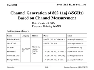
September 2014 doc.: IEEE 802.11-14/1202r0 NG60 channel model Date: 2014-09-16 Authors: Name Amichai Sanderovich Qualcomm Affiliations Address Phone email amichais@qti.qualcomm.com eitana@qualcomm.com Alecsander Eitan Qualcomm james.wang@mediatek.com James Wang Mediatek Lei.Huang@sg.panasonic.com Lei Huang Panasonic brianh@cisco.com Brian Hart Cisco Submission Slide 1 Amichai Sanderovich, Qualcomm
September 2014 doc.: IEEE 802.11-14/1202r0 Abstract Channel bonding MIMO in mmWave Simulation Example Channel model for MIMO @ NG60 Submission Slide 2 Amichai Sanderovich, Qualcomm
September 2014 doc.: IEEE 802.11-14/1202r0 Channel bonding Channel bonding is simple technique to multiply the transmission rate Use of contiguous band is preferred for hardware. Less crowded than 2.4 or 5 GHz, interference and spectral mask issues less pivotal as in 5G Spatial selectivity higher than in other bands, with higher scattering and diffractions e.g. 2.4G, 5G, hence less in-band interference Today ADC technology allows implementation of 5.3Gsps 6 bits ADC/DAC with <70mW Submission Slide 3 Amichai Sanderovich, Qualcomm
September 2014 doc.: IEEE 802.11-14/1202r0 MIMO in mmWave Each antenna can be either: A separated phased array subassembly Separated chain within same subassembly Many MIMO options: SVD,ML,MMSE, etc. 60 GHz MIMO has unique features: Good separation between subassemblies (>> ) Each subassembly is a configurable antenna array High bandwidth, moderate SNR: robustness to low power interference RX->TX basic feedback for multi-antenna already defined in the 802.11ad specification Submission Slide 4 Amichai Sanderovich, Qualcomm
September 2014 doc.: IEEE 802.11-14/1202r0 MIMO in mmWave Consider a 4x4 MIMO in 60GHz system in the frequency domain At receiver chain 2, the received signal is ?? ???,2= #1 #1 ?? ???,1 ?? ???,2 ?? ???,3 ?? ???,4 ???,1 0 0 #2 #2 0,???,2,..,0 ? ???,4 #3 #3 Where: ???,?: the subassembly configuration for RX-chain i, ???,?: the subassembly configuration for TX-chain i ?? ???,?: the signal transmitted through TX-chain i ?: the physical channel between each receive and transmit antenna element #4 #4 Submission Slide 5 Amichai Sanderovich, Qualcomm
September 2014 doc.: IEEE 802.11-14/1202r0 MIMO in mmWave 1. Phased arrays approximated SVD: The RF configurations approximate the singular vectors from the SVD of H Each TX antenna subassembly sends 1 stream to one RX antenna subassembly Other options such as 1->2 or 2->1 are not effective for multiple antenna subassemblies due to the directivity Feedback from RX to TX 1. TX-SS is multiplied by # TX antenna subassemblies 2. TX-SS extended feedback is multiplied by #TX antenna subassemblies 3. TX-SS is followed by multiple 802.11ad MIDC PHY Channel estimation done per stream MCS/power per stream: TX power limit per subassembly 2. 3. 4. 5. Submission Slide 6 Amichai Sanderovich, Qualcomm
September 2014 doc.: IEEE 802.11-14/1202r0 Example: simulation Double channel (3.5 GHz bandwidth) Using approximated SVD, 4 sector IDs are returned to TX Each antenna subassembly is made of 16 patch antennas arranged in two lines 4 subassemblies, each turning to different direction (as in the picture in the backup slide) All rates up to 64QAM are used Room of 4x5x2.8 [m] with a table of 3x1.2 [m] in the center and a monitor of 0.4x0.4 [m] on top of the table Submission Slide 7 Amichai Sanderovich, Qualcomm
September 2014 doc.: IEEE 802.11-14/1202r0 Example: simulation (cont) TX remains fixed at the end of the table, RX moves around 3D Ray-tracing simulation, all reflections are considered up to the 2 order reflection, including from ceiling/floor Simulator was calibrated to real-world measurements and current system parameters Maximum SINR RF configuration is used. The BB in this example does not include any multi-stream spatial equalizer Submission Slide 8 Amichai Sanderovich, Qualcomm
September 2014 Example: simulation results rate in bps doc.: IEEE 802.11-14/1202r0 Submission Slide 9 Amichai Sanderovich, Qualcomm
September 2014 Channel model for MIMO @ NG60 doc.: IEEE 802.11-14/1202r0 Use H = r H t as the channel model compact matrix compresses the false degrees of freedom from H same approach as MIMO channel models in previous standards (802.11, 3GPP etc.). Several environments: 1. Living room, strong reflectors (low ceil, concrete walls) 2. Cubical, weak reflectors (high ceil, fabric walls) 3. Large conference room 4. Outdoor Submission Slide 10 Amichai Sanderovich, Qualcomm
September 2014 Channel model for MIMO @ NG60 doc.: IEEE 802.11-14/1202r0 System options: 1. Same subassembly, several chains (1,2,3,4) 2. Several subassemblies with varying number of antennas (1,4,16,32) 3. Basic array configuration options: SNR optimal: Just maximum SNR SINR-optimal: Takes inter chains interference into account Capacity-optimal: requires a lot of feedback Will a full-duplex mode be of use ? The channel model from 802.11ad should be modified for MIMO Submission Slide 11 Amichai Sanderovich, Qualcomm
September 2014 doc.: IEEE 802.11-14/1202r0 Backup Submission Slide 12 Amichai Sanderovich, Qualcomm
September 2014 doc.: IEEE 802.11-14/1202r0 Example: a tablet system Submission Slide 13 Amichai Sanderovich, Qualcomm
September 2014 doc.: IEEE 802.11-14/1202r0 ADC/DAC FOM ADC/DAC: looking into the literature Figure of merit (FOM) Digitally assisted ADCs are common in the industry ADCs running in 5GHz BW, assuming 6 bits Power estimated is 32 mW Submission Slide 14 Amichai Sanderovich, Qualcomm
September 2014 doc.: IEEE 802.11-14/1202r0 ADC/DAC FOM A/D Converter Trends: Power Dissipation, Scaling and Digitally Assisted Architectures, B. Murmann Stanford University, Stanford, CA, IEEE 2008 Custom Integrated Circuits Conference (CICC) ADCsurvey_rev20130629a.xlsx http://www.scribd.com/doc/205265261/ADCsurvey- rev20130629a Submission Slide 15 Amichai Sanderovich, Qualcomm


