IEEE 802.11-16/0988r1 Non-EDMG Part of Preamble for MIMO in 11ay
Discover the non-EDMG portion of the preamble for MIMO in IEEE 802.11-16/0988r1 document dated July 25, 2016. Explore options for preamble frame format and channel bonding configurations in MIMO setups.
Download Presentation

Please find below an Image/Link to download the presentation.
The content on the website is provided AS IS for your information and personal use only. It may not be sold, licensed, or shared on other websites without obtaining consent from the author. If you encounter any issues during the download, it is possible that the publisher has removed the file from their server.
You are allowed to download the files provided on this website for personal or commercial use, subject to the condition that they are used lawfully. All files are the property of their respective owners.
The content on the website is provided AS IS for your information and personal use only. It may not be sold, licensed, or shared on other websites without obtaining consent from the author.
E N D
Presentation Transcript
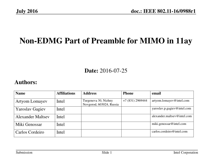
July 2016 doc.: IEEE 802.11-16/0988r1 Non-EDMG Part of Preamble for MIMO in 11ay Date: 2016-07-25 Authors: Name Affiliations Address Phone email +7 (831) 2969444 Turgeneva 30, Nizhny Novgorod, 603024, Russia artyom.lomayev@intel.com Artyom Lomayev Intel yaroslav.p.gagiev@intel.com Yaroslav Gagiev Intel alexander.maltsev@intel.com Alexander Maltsev Intel miki.genossar@intel.com Miki Genossar Intel carlos.cordeiro@intel.com Carlos Cordeiro Intel Submission Slide 1 Intel Corporation
July 2016 doc.: IEEE 802.11-16/0988r1 Introduction This presentation describes the non-EDMG portion of the preamble for MIMO in 11ay. It is based on the general frame format defined in the SFD, [1]. Submission Slide 2 Intel Corporation
July 2016 doc.: IEEE 802.11-16/0988r1 Preamble Frame Format Options The defined preamble format in [1] includes legacy part, EDMG-Header- A received in the SISO mode. The EDMG-STF and EDMG-CEF are received using MIMO mode. The legacy part of the preamble can be received and decoded by any device (legacy or EDMG). The EDMG-Header-A can be received and decoded by EDMG device in SISO mode to extract MIMO parameters. There are 2 basic options to transmit legacy preamble: Option #1: transmit the legacy preamble from one of the antennas only, switch on MIMO transmission starting from EDMG-STF; Option #2: Transmit the legacy preamble from all antennas simultaneously with time delay shift Tshift to avoid coherent signal transmission and unintentional beamforming; EDMG PPDU format, [1] L-STF L-CEF L-Header EDMG- Header-A EDMG-STF EDMG- CEF EDMG- Header-B Data AGC TRN Submission Slide 3 Intel Corporation
July 2016 doc.: IEEE 802.11-16/0988r1 Option #1 Preamble Format The preamble frame format for option #1 assumes the legacy preamble, L-Header, and EDMG-Header-A transmission for one of the streams. The antenna selection can be done based on the quality of the link, the best beamforming settings. The frame format for the M streams is shown in figure below. Stream #1 L-STF L-CEF L-Header EDMG-Header-A EDMG-STF EDMG-CEF EDMG-Header-B Stream #2 EDMG-STF EDMG-CEF EDMG-Header-B . . . . . . Stream #M EDMG-STF EDMG-CEF EDMG-Header-B Submission Slide 4 Intel Corporation
July 2016 doc.: IEEE 802.11-16/0988r1 Option #1 Preamble Format with Channel Bonding The generalization to the channel bonding with K frequency channels and M streams is shown in figure below. CH #1 L-STF L-CEF L-Header EDMG-Header-A CH #2 L-STF L-CEF L-Header EDMG-Header-A Stream #1 EDMG-STF EDMG-CEF EDMG-Header-B . . . CH #K L-STF L-CEF L-Header EDMG-Header-A . . . Stream #2 EDMG-STF EDMG-CEF EDMG-Header-B . . . Stream #M EDMG-STF EDMG-CEF EDMG-Header-B Submission Slide 5 Intel Corporation
July 2016 doc.: IEEE 802.11-16/0988r1 Option #2 Preamble Format for 2x2 MIMO Cut & copy the part of Ga to tail Ga128 Ga128 . . . -Ga128 L-CEF L-Header EDMG-Header-A EDMG-STF EDMG-CEF Tshift Stream #1 Ga128 Ga128 . . . -Ga128 L-CEF L-Header EDMG-Header-A EDMG-STF EDMG-CEF Stream #2 Ga128 Ga128 . . . -Ga128 L-CEF L-Header EDMG-Header-A EDMG-STF EDMG-CEF L-STF field Tshift some time delay between the streams, it is defined in the chips units taken @1.76 GHz, should be smaller comparing to the GI length; The part corresponding to the Tshift is used as a padding at the end of the legacy preamble part and inserted after EDMG-Header-A; Hence there is some cyclic shift by Tshift is applied which is an optimization parameter; Submission Slide 6 Intel Corporation
July 2016 doc.: IEEE 802.11-16/0988r1 Time Shift Purpose & Consequences Time shift purpose: To prevent interference between the arrays; The time shift may not be needed for the single antenna array with orthogonal (V/H) polarizations or dual arrays transmitting with different polarizations; Time shift consequences: Even for the LOS one gets a multipath channel, hence the interference issue is solved at the expense of the multipath propagation; This has a significant impact on the frame detection and headers decoding performance; Submission Slide 7 Intel Corporation
July 2016 doc.: IEEE 802.11-16/0988r1 Time Shift Requirements Time shift requirements: The total duration of the time shift for the maximum 8 streams transmission should not exceed a half of the GI duration; The Tshift value should be enough to reduce the impact of the interference; Channel frequency selectivity issue should be considered to avoid the impact on the packet detection and headers decoding; It should be an even number in order to have an integer number of samples for the OFDM after 1.5x sampling rate conversion; Proposal: It is proposed to define Tshift = 4 chips = 2.2727 ns (TBD); Tshift may be a flexible parameter depending on what type of the antenna is used, since for the orthogonal polarizations it is not needed; Submission Slide 8 Intel Corporation
July 2016 doc.: IEEE 802.11-16/0988r1 Channel Realizations with 2 Rays Delay = 1 chip Delay = 2 chips Delay = 3 chips In case of LOS, delaying of the signal corresponding to the second stream produces effective two-ray channel. Rays have almost equal power, may have different phases, and delayed by a number of chips. In that case channel has hostile frequency response with deep notches. The number of notches is equal to the delay in chips. Figures above show the frequency responses for different time delays 1, 2, and 3 chips. The phase difference between the rays is fixed and equal to = 300. Submission Slide 9 Intel Corporation
July 2016 doc.: IEEE 802.11-16/0988r1 Legacy Header Coding & Modulation The legacy header has sophisticated encoding process composed of the following steps: 64 header bits (b1,b2, , b64) is padded with zeros to the length of 504 and encoded with LDPC code with rate : b1,b2, , b64 0, 0, , 0440 p1,p2, , p168 The output is calculated parity of length 168 bits (p1,p2, , p168); Then 2 codewords cs1 and cs2 are defined as concatenation of systematic header bits (b1,b2, , b64) and parity bits with discarded tail and middle parts accordingly: CS1 b1,b2, , b64 p1,p2, , p160 CS2 b1,b2, , b64 p1,p2, , p152, p161,p162, , p168 Finally, cs1 and cs2 are joined into the codeword cs = (cs1, cs2); It is modulated using /2-BPSK modulation and appended with GI, the SC symbol is repeated 2 times. The legacy header has a robust encoding and may operate under the hard multipath channel condition. However additional justification by simulations is required. Submission Slide 10 Intel Corporation
July 2016 doc.: IEEE 802.11-16/0988r1 Option #2 Preamble Format for 4x4 MIMO 3*Tshift Stream #1 Ga128 Ga128 . . . -Ga128 L-CEF L-Header EDMG-Header-A EDMG-STF EDMG-CEF 2*Tshift Stream #2 Ga128 Ga128 . . . -Ga128 L-CEF L-Header EDMG-Header-A EDMG-STF EDMG-CEF Tshift Stream #3 Ga128 Ga128 . . . -Ga128 L-CEF L-Header EDMG-Header-A EDMG-STF EDMG-CEF Stream #4 Ga128 Ga128 . . . -Ga128 L-CEF L-Header EDMG-Header-A EDMG-STF EDMG-CEF L-STF field The legacy part of each stream is delayed by a multiple integral of Tshift time. Legacy part of stream #4 is delayed relative to the stream #1 by 3*Tshift time shift. For 8 streams the generalization is straightforward, the maximum delay will be 7*Tshift = 24 chips = 15.9 ns. This is less than a half of the GI = 64 chips = 36.3636 ns. Submission Slide 11 Intel Corporation
July 2016 doc.: IEEE 802.11-16/0988r1 Option #2 2x2 MIMO & Channel Bonding 2x Tshift CH #1 Ga128 Ga128 . . . -Ga128 L-CEF L-Header EDMG-Header-A Stream #1 EDMG-STF EDMG-CEF CH #2 Ga128 Ga128 . . . -Ga128 L-CEF L-Header EDMG-Header-A CH #1 Ga128 Ga128 . . . -Ga128 L-CEF L-Header EDMG-Header-A Stream #2 EDMG-STF EDMG-CEF CH #2 Ga128 Ga128 . . . -Ga128 L-CEF L-Header EDMG-Header-A L-STF field Figure above shows preamble frame format for combination of 2x2 MIMO and channel bonding 2x. Similar to the MIMO frames presented at the previous slides padding is done for the legacy part. Padding is identical for all bonded channels pertained to the same stream. Submission Slide 12 Intel Corporation
July 2016 doc.: IEEE 802.11-16/0988r1 Simulation Assumptions L-Header error rate performance is analyzed, 2 options for preamble definition are compared. Option #1: Line Of Sight (LOS) channel, transmission is done using single antenna, channel has single tap in time domain and an ideal flat characteristic in frequency domain; Option #2: LOS channel, transmission is done using 2 (or 4) antennas, channel has 2 (or 4) rays delayed by the Tshift in time domain and selective characteristic in frequency domain; In this case one has 2 (or 4) times more power comparing to the option #1, hence it leads to the advantage in 3 dB (or 6 dB) in SNR; Channel model: Channel has 1, 2 or 4 rays of equal power, phases of rays are independent random variables in [0, 2 ], rays are delayed by Tshift time intervals; Submission Slide 13 Intel Corporation
July 2016 doc.: IEEE 802.11-16/0988r1 Simulation Results 2 Streams Header Error Rate (HER) performance comparison Figure compares Header Error Rate performance for 2 options; Option #1: flat channel (gray curve); Option #2: 2 ray channel (colored curves), it has 2 times higher power, hence 3 dB advantage in SNR; The performance changes not dramatically with changing of T shift = 2, 4, 6 chips; Option #2 has an advantage in ~2.0 dB for HER = 10-3; Submission Slide 14 Intel Corporation
July 2016 doc.: IEEE 802.11-16/0988r1 Simulation Results 4 Streams Header Error Rate (HER) performance comparison Figure compares Header Error Rate performance for 2 options; Option #1: flat channel (gray curve); Option #2: 4 ray channel (colored curves), it has 4 times higher power, hence 6 dB advantage in SNR; The performance changes not dramatically with changing of T shift = 2, 4, 6 chips; Option #2 has an advantage in ~3.8 dB for HER = 10-3; Submission Slide 15 Intel Corporation
July 2016 doc.: IEEE 802.11-16/0988r1 Conclusions This presentation proposes a definition of the non-EDMG portion of the preamble for MIMO in 11ay. Two options for the non-EDMG preamble were considered. It was shown that the option with the cyclic shift has an advantage in terms of SNR required to achieve a reliable header reception. Submission Slide 16 Intel Corporation
July 2016 doc.: IEEE 802.11-16/0988r1 Straw Poll Would you agree to insert the following in section 7 of the SFD: For SC MIMO transmissions, the 11ay specification shall support a preamble structure with cyclic shift. A cyclic shift TiSC value is used for the L-STF, L-CEF, L-Header and EDMG-Header-A fields of the PPDU for stream i out of a total of N streams, where 1 i N. TiSC is defined in SC chip units at 1.76 GHz for single channel or multiple channels transmission. TiSC shall be inserted after EDMG-Header-A. The particular value for each configuration is TBD. Submission Slide 17 Intel Corporation
July 2016 doc.: IEEE 802.11-16/0988r1 References 1. 11-15-1358-04-00ay-specification-framework-for-tgay Submission Slide 18 Intel Corporation

