IEEE 802.11-20/0576r1 Coordinated Spatial Reuse Protocol Overview
Learn about the IEEE 802.11-20/0576r1 protocol proposing a general coordinated spatial reuse approach for multi-AP setups. The protocol covers phases like interference measurement, transmission coordination, and more to enhance performance. Dive into details to understand the C-SR general procedure and assumptions guiding this innovative protocol.

Download Presentation

Please find below an Image/Link to download the presentation.
The content on the website is provided AS IS for your information and personal use only. It may not be sold, licensed, or shared on other websites without obtaining consent from the author. If you encounter any issues during the download, it is possible that the publisher has removed the file from their server.
You are allowed to download the files provided on this website for personal or commercial use, subject to the condition that they are used lawfully. All files are the property of their respective owners.
The content on the website is provided AS IS for your information and personal use only. It may not be sold, licensed, or shared on other websites without obtaining consent from the author.
E N D
Presentation Transcript
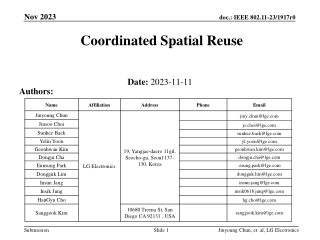
April 2020 doc.: IEEE 802.11-20/0576r1 Coordinated Spatial Reuse (C-SR) Protocol Date: 2020-05-07 Authors: Name Affiliations Address Phone email 2840 Junction Ave, San Jose, CA 95134 yongho.seok@mediatek .com Yongho Seok MediaTek Inc. Gary Anwyl MediaTek Inc. Jianhan Liu MediaTek Inc. James Wang MediaTek Inc. Kaiying Lu MediaTek Inc. James Yee MediaTek Inc. Thomas Pare MediaTek Inc. Submission Slide 1 Yongho Seok, MediaTek
April 2020 doc.: IEEE 802.11-20/0576r1 Motivation Previous contributions [1-3] showed the performance gain of the multi-AP coordinated spatial reuse. This contribution proposes a general coordinated spatial reuse protocol. Submission Slide 2 Yongho Seok, MediaTek
April 2020 doc.: IEEE 802.11-20/0576r1 Assumptions An AP does not manage its OBSS STAs APs participating in a C-SR are in range of each other TXOP Owner orchestrates the C-SR transmission in a SR TXOP No backhaul coordination between APs, instead the coordination via over-the-air signaling Submission Slide 3 Yongho Seok, MediaTek
April 2020 doc.: IEEE 802.11-20/0576r1 C-SR General Procedure The C-SR general procedure consist of C-SR phse1 (interference measurement & report) and C-SR phase 2 (C-SR transmission) in a single TXOP. But, the C-SR phase 1 for the interference measurement & report is not always required before the C-SR transmission. It can be skipped. TXOP AP1 Trigger Trigger A-MPDU C-SR Announcement STA11 TB PPDU BA C-SR transmission CCA AP2 A-MPDU Measure RSSI Per-RU RSSI Report STA21 BA C-SR Phase 1: Interference measurement & report C-SR Phase 2: C-SR Transmission Submission Slide 4 Yongho Seok, MediaTek
April 2020 doc.: IEEE 802.11-20/0576r1 C-SR Phase 1: Interference measurement & report A sharing AP among the AP candidate set for the C-SR solicits TB PPDUs (e.g., BSR, BFR) from its associated STAs. The sharing AP specifies in the User Info fields in the Trigger frame one or more shared AP(s) among the AP candidate set to request the RSSI measurement on each RU allocated in the soliciting Trigger frame. The sharing AP and the requested shared AP(s) measure the RSSI on each RU, and the shared AP(s) reports to the sharing AP the Per-RU RSSI Report frame having the measurement results. The sharing AP may send the Trigger frame to get the Per-RU RSSI Reports from multiple shared APs simultaneously. Submission Slide 5 Yongho Seok, MediaTek
April 2020 doc.: IEEE 802.11-20/0576r1 C-SR Phase 1: Interference measurement & report Since the shared AP (e.g., AP2) reports RSSIap2 in the Per-RU RSSI Report frame to the sharing AP (e.g., AP1), the sharing AP can calculate the interference level (RSSItarget RSSIap2) caused by the shared AP (e.g., AP2) on its associated STA (STA11) when the AP1 and the AP2 simultaneously transmit the downlink frames at the same transmit power. NOTE- See the detail in the Slide 18. Submission Slide 6 Yongho Seok, MediaTek
April 2020 doc.: IEEE 802.11-20/0576r1 C-SR Phase 1: Interference measurement & report Each sharing AP among the AP candidate set for the C-SR performs the interference measurement and report procedure at its owned TXOP. The shared AP can sequentially perform the interference measurement and report procedure at the sharing AP's TXOP when the sharing AP allows. The first Per-RU RSSI Report contains the measured RSSI on the shared AP. The second Per-RU RSSI Report contains the measured RSSI on the sharing AP. Submission Slide 7 Yongho Seok, MediaTek
April 2020 doc.: IEEE 802.11-20/0576r1 C-SR Phase 1: Interference measurement & report The sharing AP and shared AP can perform the interference measurement and report procedure simultaneously in an OFDMA manner when the sharing AP allows. The STAs associated with the shared AP respond with the TB PPDU when the Trigger frame sent by the sharing AP requests to perform the interference measurement and report procedure. The first Per-RU RSSI Report contains the measured RSSI on the shared AP side. The second Per-RU RSSI Report contains the measured RSSI on the sharing AP side. Submission Slide 8 Yongho Seok, MediaTek
April 2020 doc.: IEEE 802.11-20/0576r1 C-SR Phase 2: C-SR Transmission A sharing AP among the AP candidate set for the C-SR initiates the C-SR transmission by sending the C-SR Announcement frame. The shared AP performs the CCA during the SIFS after the C-SR Announcement frame. The shared AP disregards the NAV set by the sharing AP. If both the physical and virtual CS are idle, the shared AP exchanges frames with its associated STAs during the C-SR duration time within the C-SR bandwidth. Submission Slide 9 Yongho Seok, MediaTek
April 2020 doc.: IEEE 802.11-20/0576r1 C-SR Phase 2: C-SR Transmission C-SR DL transmission C-SR UL TB transmission Submission Slide 10 Yongho Seok, MediaTek
April 2020 doc.: IEEE 802.11-20/0576r1 C-SR Phase 2: C-SR Transmission The C-SR Announcement frame specifies for each shared AP that is granted in the C-SR transmission the following constraints: The C-SR duration (in units of TU). The C-SR bandwidth (P20, P40, P80, P160, P240, P320). The C-SR maximum transmit power of shared AP (in units of dBm). The transmit power of the shared AP shall be less than or equal to the C-SR maximum transmit power of shared AP. When the sharing AP schedules the downlink PPDU, the C-SR maximum transmit power of shared AP is used for limiting the interference level caused by the shared AP on the sharing AP s scheduled STA. The C-SR transmit power of sharing AP (in units of dBm). When the shared AP schedules the downlink C-SR transmission, the C-SR transmit power of the sharing AP is used for calculating the interference level caused by the sharing AP on the scheduled STA. Submission Slide 11 Yongho Seok, MediaTek
April 2020 doc.: IEEE 802.11-20/0576r1 C-SR Phase 2: C-SR Transmission The C-SR Announcement frame specifies for each shared AP that is granted in the C-SR transmission the following constraints: The C-SR tolerable maximum interference signal strength (in units of dBm). The total interference signal strength effecting to the sharing AP shall be less than the C-SR tolerable maximum interference signal strength indicated in the C-SR Announcement frame. If the C-SR tolerable maximum interference signal strength is set to 0, the shared AP in the C-SR TXOP can t solicit TB PPDUs except for the TB PPDU for the control response frame. The C-SR shared AP interference signal strength (in units of dBm). The C-SR shared AP interference signal strength indicates the total interference signal strength effecting from the sharing AP to the shared AP. The C-SR shared AP interference signal strength is used on the scheduling algorithm on the shared AP (e.g., the target STA, the resource unit, and the MCS). Submission Slide 12 Yongho Seok, MediaTek
April 2020 doc.: IEEE 802.11-20/0576r1 C-SR Phase 2: C-SR Transmission Since the sharing AP (e.g., AP1) reports RSSIap1 in the Per-RU RSSI Report frame to the shared AP (e.g., AP2), the shared AP can calculate the interference level (RSSIap1 RSSItarget) caused by the TB PPDU effecting to the sharing AP. The UL Target RSSI field in the Trigger frame shall be set to the value meeting the C-SR tolerable maximum interference signal strength constraint. If the total interference level caused by the TB PPDUs effecting to the sharing AP is greater than or equal to the C-SR tolerable maximum interference signal strength, the shared AP shall not solicit additional TB PPDUs. Submission Slide 13 Yongho Seok, MediaTek
April 2020 doc.: IEEE 802.11-20/0576r1 Simulation Setup Topology AP/STA Configuration 4T AP, 2R STA, 2ss TX = +21 dBm per AP Channel 80MHz, D-NLOS TGn Path loss model Metric Sum Goodput Modes Coordinated OFDMA (C-OFDMA) - Each AP TXs in a different 20M RU Spatial Reuse (SR) All APs transmit simultaneously at full power Coordinated Spatial Reuse with TPC (CSR+TPC) - Exhaustive search to select Transmit Power Control (TPC) for each AP that maximizes sum goodput. MCS and TPC selection is based on CSI for all AP-STA combinations Coordinated Spatial Reuse with TPC (CSR+PL TPC) Same as CSR+TPC but TPC and MCS selection is based on path loss Four APs AP-AP distance = 20m BSS Radius = 10m Randomly drop a STA in BSS Submission Slide 14 Yongho Seok, MediaTek
April 2020 doc.: IEEE 802.11-20/0576r1 Simulation Results Higher Goodput for CSR+TPC versus SR. CSR performance when Pathloss is used to select MCS and TPC is nearly the same as the performance when full CSI is used. Submission Slide 15 Yongho Seok, MediaTek
April 2020 doc.: IEEE 802.11-20/0576r1 Conclusion The proposed C-SR protocol needs the support from only AP. Also, no PHY change is needed. The STA does not needs any protocol update. The protocol overhead is minimized because the existing 11ax UL MU procedure is reused. In single TXOP, only the Per-RU RSSI Report frame (even it is not required for every TXOPs) and the C-SR Announcement frame are additional overhead. Comparing with other multi-AP features, only C-SR can achieve both the low complexity and high performance (throughput and latency) gain. So, we propose C-SR as the multi-AP R1 feature. Submission Slide 16 Yongho Seok, MediaTek
April 2020 doc.: IEEE 802.11-20/0576r1 Referecnes [1] https://mentor.ieee.org/802.11/dcn/20/11-20-0073-00- 00be-on-coordinated-spatial-reuse-in-11be.pptx [2] https://mentor.ieee.org/802.11/dcn/20/11-20-0033-01- 00be-coordinated-spatial-reuse-operation.pptx [3] https://mentor.ieee.org/802.11/dcn/20/11-20-0107-01- 00be-multi-ap-coordination-for-spatial-reuse.pptx Submission Slide 17 Yongho Seok, MediaTek
April 2020 doc.: IEEE 802.11-20/0576r1 Backup Submission Slide 18 Yongho Seok, MediaTek
April 2020 doc.: IEEE 802.11-20/0576r1 C-SR Phase 1: Interference measurement & report A sharing AP among the AP candidate set for the C-SR solicits TB PPDUs (e.g., BSR, BFR) from its associated STAs. The sharing AP specifies in the User Info fields in the Trigger frame one or more shared AP(s) among the AP candidate set to request the RSSI measurement on each RU allocated in the soliciting Trigger frame. The interference measurement dialog token is also included in the User Info field in the Trigger frame to identify the interference measurement and report transaction. The requested shared AP(s) measures the RSSI on each RU and reports to the sharing AP the Per-RU RSSI Report frame having the measurement results and the associated interference measurement dialog token. The measurement and report can be in the same or different TXOPs. The sharing AP may send the Trigger frame to solicit one or more the Per-RU RSSI Report frames from multiple shared APs. Slide 19 Submission Yongho Seok, MediaTek
April 2020 doc.: IEEE 802.11-20/0576r1 C-SR Phase 1: Interference measurement & report The Per-RU RSSI Report frame format Action (Per-RU RSSI Report) Category (Public Action) Interference Measurement Dialog Token Number Of Reported RUs AID Associated With Reported RU Measured RSSI On Reported RU 1 octet 1 octet 1 octet 1 octet 2 octet 1 octet Repeated as indicated in the Number Of Reported RSSIs field The RA field is set to the MAC address of the sharing AP that requests the RSSI measurement on each RU allocated in the soliciting Trigger frame. The TA field is set to the MAC address of the shared AP that is sending the Per-RU RSSI Report frame. The Interference Measurement Dialog Token field is set to the same value as in the Interference Measurement Dialog Token field in the soliciting Trigger frame. The AID Associated With Reported RU field is set to the AID associated with the reported RU, that is obtained from the AID12 subfield associated with the reported RU in the soliciting Trigger frame. The Measured RSSI On Reported RU field is set to the measured RSSI on the reported RU. Submission Slide 20 Yongho Seok, MediaTek
April 2020 doc.: IEEE 802.11-20/0576r1 C-SR Phase 1: Interference measurement & report At completion of interference and measurement reporting each AP can compile the following SIR table using the appropriate information. This information can allow either DL or UL C-SR operation The SIR values can be controlled by adjusting TXPWRAP1 and TXPWRAP2. SIR Table From AP1 AP2 To STA 11 (TXPWRAP1 - TXPWRAP2)+ (RSSISTA11->AP1 RSSISTA11->AP2) (TXPWRAP2 TXPWRAP1)+ (RSSISTA11->AP2 RSSISTA11->AP1) STA 12 (TXPWRAP1 - TXPWRAP2)+ (RSSISTA12->AP1 RSSISTA12->AP2) (TXPWRAP1 - TXPWRAP2)+ (RSSISTA21->AP1 RSSISTA21->AP2) (TXPWRAP1 - TXPWRAP2)+ (RSSISTA22->AP1 RSSISTA22->AP2) (TXPWRAP2 TXPWRAP1)+ (RSSISTA12->AP2 RSSISTA12->AP1) (TXPWRAP2 TXPWRAP1)+ (RSSISTA21->AP2 RSSISTA21->AP1) (TXPWRAP2 TXPWRAP1)+ (RSSISTA22->AP2 RSSISTA22->AP1) NOTE- TXPWRAP1is the TX Power of AP1 (dBm). TXPWRAP2is the TX Power of AP2 (dBm). RSSISTAi->APj is the received signal strength indicator (dB) at APj of the signal sent by the STAi. STA 21 STA 22 Submission Slide 21 Yongho Seok, MediaTek