IEEE 802.11-21/162r0 Static Puncture Signalling Details
This document explores the placement of static puncture information within an EHT BSS for IEEE 802.11-21/162r0. It delves into two potential options for indicating static puncture info and discusses their implications in detail.
Download Presentation

Please find below an Image/Link to download the presentation.
The content on the website is provided AS IS for your information and personal use only. It may not be sold, licensed, or shared on other websites without obtaining consent from the author. If you encounter any issues during the download, it is possible that the publisher has removed the file from their server.
You are allowed to download the files provided on this website for personal or commercial use, subject to the condition that they are used lawfully. All files are the property of their respective owners.
The content on the website is provided AS IS for your information and personal use only. It may not be sold, licensed, or shared on other websites without obtaining consent from the author.
E N D
Presentation Transcript
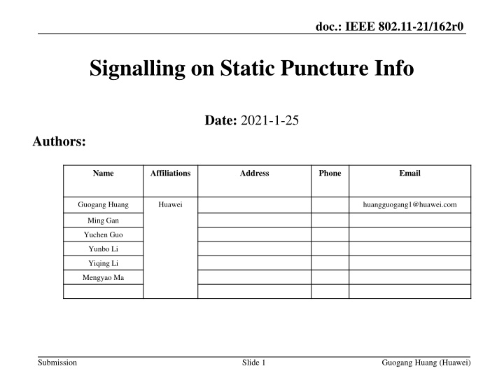
doc.: IEEE 802.11-21/162r0 Signalling on Static Puncture Info Date: 2021-1-25 Authors: Name Affiliations Address Phone Email Guogang Huang Huawei huangguogang1@huawei.com Ming Gan Yuchen Guo Yunbo Li Yiqing Li Mengyao Ma Submission Slide 1 Guogang Huang (Huawei)
doc.: IEEE 802.11-21/162r0 Introduction We had agreed that an EHT BSS can advertise different BSS bandwidths respectively for EHT STA and non-EHT STA especially when static puncture is applied [1]. But the specific location of static puncture info is still undecided In this contribution, we want to discuss where to carry the Puncture info and how to signal the Puncture info Submission Slide 2 Guogang Huang (Huawei)
doc.: IEEE 802.11-21/162r0 Discussion Generally, there are two possible options for the location of static puncture info Option 1. Explicitly indicated through EHT Operation element Option 2. Implicitly indicated through Transmit Power Envelope element In the following, we will respectively discuss the above two options in detail. Submission Slide 3 Guogang Huang (Huawei)
doc.: IEEE 802.11-21/162r0 Option 1 Explicitly indicated through EHT Operation element Indication Rules. For EHT Operation element, use a channel bitmap with the length of 2 octets 0: the corresponding 20 MHz channel is punctured 1: the corresponding 20 MHz channel is not punctured If some 20 channels have different PSD, then only the PSD info on unpunctuated 20 MHz channels is indicated in Transmit Power Envelope element [2]. Specifically, Use a reserved value (e.g. 5) to indicate values of N greater than 8. If all 20 channels have the same PSD, then we can directly indicate the EIRP info for each typical channel width by setting N=0 //note: defined in 11ax Submission Slide 4 Guogang Huang (Huawei)
doc.: IEEE 802.11-21/162r0 Option 2 Implicitly indicated through Transmit Power Envelope element Indication Rules. Use a reserved value (e.g. 5) to indicate values of N greater than 8. If N is greater than 8, the Maximum Transmit PSD 1-8 subfields correspond to the 20 MHz channels from lowest to highest frequency, respectively, within the 160 MHz channel containing the primary 20 MHz channel. //note: defined in 11ax The Maximum Transmit PSD X subfield is encoded as an 8-bit 2s complement signed integer. The value 128 indicates that the corresponding 20 MHz channel cannot be used for transmission[2]. //note: defined in 11ax Submission Slide 5 Guogang Huang (Huawei)
doc.: IEEE 802.11-21/162r0 Example For a 320 MHz EHT BSS, assume that CH 4, 10, 13 are punctured, as shown in the left Figure If some 20 channels have different PSD, then the corresponding Transmit Power Envelope element is set as the right Figure Note that the PSD info on each 20 MHz channel (including punctuated and unpunctuated channel) need to be included Frequency Submission Slide 6 Guogang Huang (Huawei)
doc.: IEEE 802.11-21/162r0 Comments Option 2 has limitations/drawbacks as following: We only can use indication manner 1 (EIRP PSD) and cannot use indication manner 2 (EIRP) Possibly leading to multiple TPE elements be carried in the same Beacon to overcome this issue, in which case additional rules need to be specified as to what values the multiple TPEs need to be set. HE STAs in 6 GHz band might have issues parsing the indication manner 1 of the TPE when N is >8. Even when all 20 MHz channels have same PSD, we cannot directly indicate the max TX power for each typical channel width, i.e. 20 MHz, 40 MHz, 80 MHz,160 MHz and 320 MHz Forced overhead increase in Beacons because Generally, APs only include one PSD value applicable to all channels or use indication manner 2 (EIRP) While enablement of Static puncture with this Option would require either or both of the following Inclusion of multiple TPEs (one for EIRP and additional ones for static puncture bitmap signaling) Inclusion of multiple PSDs per channel to indicate punctured info. (e.g., to signal a 16-bit puncture would require at least 16 octets) Maximum Transmit Power For 320 MHz Submission Slide 7 Guogang Huang (Huawei)
doc.: IEEE 802.11-21/162r0 Comments Option 1 has the following pros Lower signaling overhead compared with Option 2 It is simpler Does not need to add multiple IEs/modify existing IEs, to tackle different use cases and ensure backwards compliance. Submission Slide 8 Guogang Huang (Huawei)
doc.: IEEE 802.11-21/162r0 Reference [1] 11-20-0680-02-00be-operating-bandwidth-indication-for-eht-bss.pptx [2] Draft P802.11ax_D8.0 Submission Slide 9 Guogang Huang (Huawei)
doc.: IEEE 802.11-21/162r0 SP 1 Do you agree to include a 2-octet Static Puncture Bitmap field within EHT Operation element? Yes No Abstain Submission Slide 10 Guogang Huang (Huawei)

