IEEE 802.11-24/1124r2 Aug 2024 Headroom Reason Reporting
Explore the challenges faced by APs in managing client transmission power levels for spatial reuse in TB PPDUs. Learn about the proposed solution to enable clients to signal when Local max TX power levels affect TB PPDU Headroom, optimizing link-level throughput and spatial reuse.
Download Presentation

Please find below an Image/Link to download the presentation.
The content on the website is provided AS IS for your information and personal use only. It may not be sold, licensed, or shared on other websites without obtaining consent from the author. If you encounter any issues during the download, it is possible that the publisher has removed the file from their server.
You are allowed to download the files provided on this website for personal or commercial use, subject to the condition that they are used lawfully. All files are the property of their respective owners.
The content on the website is provided AS IS for your information and personal use only. It may not be sold, licensed, or shared on other websites without obtaining consent from the author.
E N D
Presentation Transcript
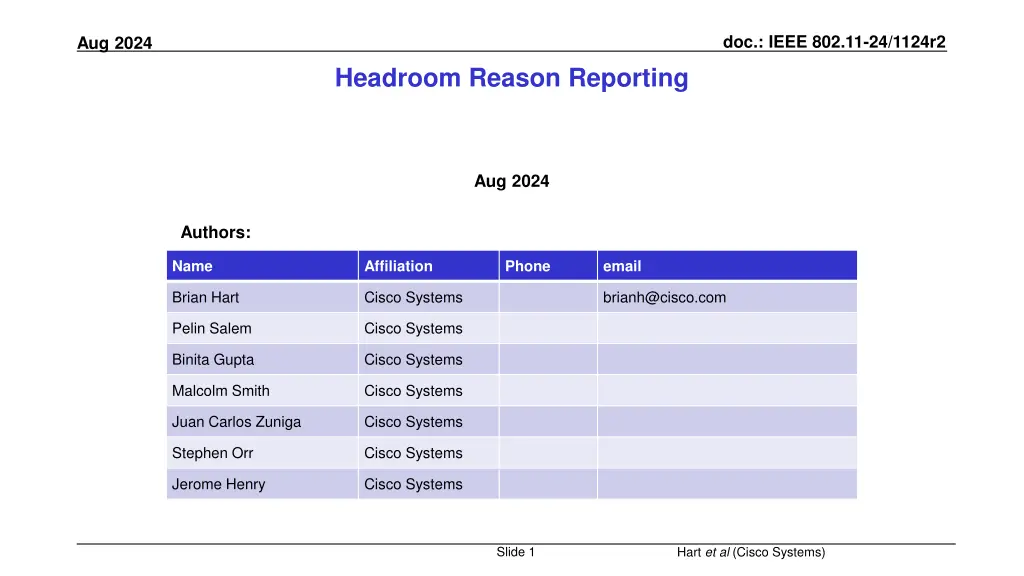
doc.: IEEE 802.11-24/1124r2 Aug 2024 Headroom Reason Reporting Aug 2024 Authors: Name Affiliation Phone email Brian Hart Cisco Systems brianh@cisco.com Pelin Salem Cisco Systems Binita Gupta Cisco Systems Malcolm Smith Cisco Systems Juan Carlos Zuniga Cisco Systems Stephen Orr Cisco Systems Jerome Henry Cisco Systems Slide 1 Hart et al (Cisco Systems)
doc.: IEEE 802.11-24/1124r2 Aug 2024 Executive Summary Situation In TB PPDUs, client TX power is subject to 1) Trigger-based controls and 2) Local max TX power level (Local TPC) for spatial reuse, among other constraints Problem AP cannot determine when these two controls are clashing When clashing, the client may transmit TB PPDUs at lower-than-requested powers, with a lowered reliable MCS and thence lower throughput The AP is unable to determine the trade-off between link-level throughput and spatial reuse Solution Enable the client to signal whenever a Local max TX power level is causing the TB PPDU Headroom to be 0 dB Slide 2 Hart et al (Cisco Systems)
doc.: IEEE 802.11-24/1124r2 Aug 2024 Situation AP triggers a client at an implied transmit power level, but the client cannot always achieve the power level APs influence client transmission power in TB PPDUs via two fields in the Trigger frame: AP Tx Power field // from which clients can determine pathloss UL Target Receive Power field // given this and the pathloss, a client can determine its TX power The client has minimum and maximum power limits for a given transmission: The transmit power of the HE TB PPDU is further subject to a STA s minimum and maximum transmit power limit due to hardware capability, regulatory requirements, and local maximum transmit power levels (see 11.7.5 (Specification of regulatory and local maximum transmit power levels)) as well as non-IEEE-802.11 in-device coexistence requirements The client can signal when a max/min limit is reached via the UPH Control subfield (in A-Control): UL Power Headroom field (0 indicates no headroom) Minimum Transmit Power Flag field (Boolean) See 26.5.2.4 (A-MPDU contents in an HE TB PPDU), 27.3.15.2 (Power precorrection), 9.2.4.7.5 (UPH Control) [1] Slide 3 Hart et al (Cisco Systems)
doc.: IEEE 802.11-24/1124r2 Aug 2024 Situation Traditional Power Control remains pre-eminent in dense deployments Although 802.11ax added the BSS Color concept to the mainstream 802.11 bands and defined the several Spatial Reuse mechanisms, the customer experience has been disappointing With little adoption; in a loose sense the Multi-AP Coordination (MAPC) area is an attempted do-over In the meantime, dense networks in the same administrative domain continue to use the traditional techniques: Each AP unilaterally lowers its power from its maximum so neighboring cochannel BSSs avoid CCA-based deferral (i.e., enables spatial reuse), and thereby the AP promotes less interference, lower latency, greater QoS and higher system throughput when needed While maintaining enough power for good AP coverage overlap to provide continuous coverage for roaming APs broaden the spatial use opportunities by sending Local max TX power level to clients Signaled via Transmit Power Envelope elements See 11.7.5 (Specification of regulatory and local maximum transmit power levels), 11.7.6 (Transmit power selection), 9.4.2.160 (Transmit Power Envelope element) (1) Lowered AP power so APs see each other at < -82 dBm / P20 for Spatial Reuse (2) Local TPE elements so BSSs see each other at < -82 dBm / P20 (2) Local TPE elements so BSSs see each other at < -82 dBm / P20 (3) Broadened availability of Spatial Reuse Slide 4 Hart et al (Cisco Systems)
doc.: IEEE 802.11-24/1124r2 Aug 2024 Problem The AP s local maximum transmit power level and UL Target Receive Power field can be inconsistent On the one hand, in a Trigger frame, the AP might solicit a client to transmit at an implied power level (via the AP Tx Power field and UL Target Receive Power fields) On the other hand, the AP s Local max TX power level signaling might preclude use of that implied power level Problem: the AP is left in the dark. (1) 60 dB pathloss; Max AP antenna gain = 5dB, actual AP antenna gain towards client = 4 dB // the difference is not important here max client antenna gain = 2 dB, actual client antenna gain towards AP = 1 dB // the difference is not important here (2) Local TPE indicates 5 dBm EIRP (3) AP Tx Power = 0 dBm conducted, UL Target RSSI Power = -45 dBm (4) Client measures RSSI = 0+4-60+1=-55 dBm; calculates PL = pathloss (less actual antenna gains) as 0 - -55 = 55 dB. Thus, Trigger frame asks client to transmit at -45 + 55 = 10 dBm conducted. (5) Thus, requirements of Trigger frame and Local TPE clash; Local TPE tells client to not transmit at greater than 5-2 = 3 dBm conducted. (6) UL TB PPDU sent at 3 dBm conducted << 10 dBm conducted sought. Slide 5 Hart et al (Cisco Systems)
doc.: IEEE 802.11-24/1124r2 Aug 2024 Solution Enable the Client to report whenever 0 dB of headroom is due to the Local max TX power level We propose that the Client should be enabled to report whenever 0 dB of headroom is due to the Local max TX power level Via allocating a reserved bit in the UPH Control subfield B0 B4 B5 B6 B6-B7 UL Power Headroom Minimum Transmit Power Flag 1 Zero Headroom Due To Local Max TX Power 1 Reserved Bits: 5 21 Enables the AP to better understand how to balance the benefits from spatial reuse versus reduced UL power (and thence reduced UL MCS) Slide 6 Hart et al (Cisco Systems)
doc.: IEEE 802.11-24/1124r2 Aug 2024 Summary We show that the AP is flying blind when trying to balance: Improved system throughput via Local max TX power level Improve link level throughput via a higher UL Target RSSI Power UL Power Headroom does not report a reason when 0 dB of headroom is reached Which is mostly fine: the AP can t change the client HW or regulations, etc But when the reason for 0 dBm headroom is the AP s Local max TX power level signaling (via TPE elements), there should be a way for the client to notify the AP so the AP can better understand and optimize the impact of its Local max TX power level and UL Target RSSI Power signaling We show this gap can easily and naturally be addressed via assigning a reserved bit in the UPH Control subfield Slide 7 Hart et al (Cisco Systems)
doc.: IEEE 802.11-24/1124r2 Aug 2024 References [1] 802.11REVme Draft 5.0 Slide 8 Hart et al (Cisco Systems)
doc.: IEEE 802.11-24/1124r2 Aug 2024 Strawpoll 1 Do you agree to add the following text to the 11bn SFD: The 802.11bn amendment will define a way for a non-AP STA to notify an AP when the STA s 0 dB of UL power headroom is due to the STA s Local max TX power level. Y / N / A Slide 9 Hart et al (Cisco Systems)
doc.: IEEE 802.11-24/1124r2 Aug 2024 Backup Slide 10 Hart et al (Cisco Systems)
doc.: IEEE 802.11-24/1124r2 Aug 2024 When it works and doesn t work (1) 50 dB pathloss; Max AP antenna gain = 5dB, actual AP antenna gain towards client = 4 dB // the difference is not important here max client antenna gain = 2 dB, actual client antenna gain towards AP = 1 dB // the difference is not important here (2) Local TPE indicates 5 dBm EIRP (3) AP Tx Power = 0 dBm conducted, UL Target RSSI Power = -45 dBm (4) Client measures RSSI = 0+4-50+1 = -45 dBm; calculates PL = pathloss (less actual antenna gains) as 0 - -45 = 45 dB. Thus, Trigger frame asks client to transmit at -45 + 45 = 0 dBm conducted. (5) Requirements of Trigger frame and Local TPE are consistent (since Local TPE tells client to not transmit at greater than 5-2 = 3 dBm conducted). (6) UL TB PPDU sent at 0 dBm conducted as sought. (1) 60 dB pathloss; Max AP antenna gain = 5dB, actual AP antenna gain towards client = 4 dB // the difference is not important here max client antenna gain = 2 dB, actual client antenna gain towards AP = 1 dB // the difference is not important here (2) Local TPE indicates 5 dBm EIRP (3) AP Tx Power = 0 dBm conducted, UL Target RSSI Power = -45 dBm (4) Client measures RSSI = 0+4-60+1 = -55 dBm; calculates PL = pathloss (less actual antenna gains) as 0 - -55 = 55 dB. Thus, Trigger frame asks client to transmit at -45 + 55 = 10 dBm conducted. (5) Thus, requirements of Trigger frame and Local TPE clash; Local TPE tells client to not transmit at greater than 5-2 = 3 dBm conducted. (6) UL TB PPDU sent at 3 dBm conducted << 10 dBm conducted sought. Slide 11 Hart et al (Cisco Systems)

