IEEE 802.11-24/1789r0 CoBF for Improved Wireless Communication
Explore the benefits of partial nulling over full nulling in IEEE 802.11 networks, with a focus on feedback types for interference mitigation. Analyze separate and joint channel decomposition approaches for efficient communication in multi-antenna systems. Discover how precoder design plays a crucial role in enhancing signal quality and reducing interference.
Download Presentation

Please find below an Image/Link to download the presentation.
The content on the website is provided AS IS for your information and personal use only. It may not be sold, licensed, or shared on other websites without obtaining consent from the author. If you encounter any issues during the download, it is possible that the publisher has removed the file from their server.
You are allowed to download the files provided on this website for personal or commercial use, subject to the condition that they are used lawfully. All files are the property of their respective owners.
The content on the website is provided AS IS for your information and personal use only. It may not be sold, licensed, or shared on other websites without obtaining consent from the author.
E N D
Presentation Transcript
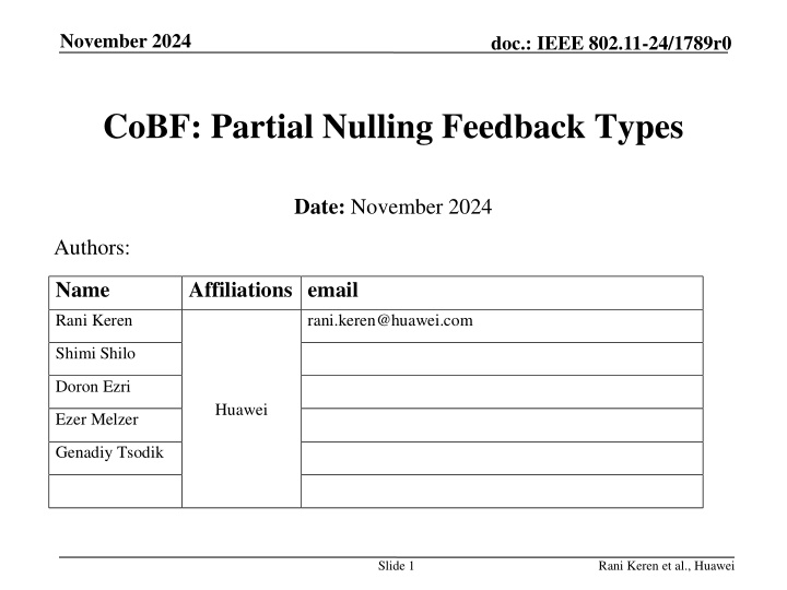
November 2024 doc.: IEEE 802.11-24/1789r0 CoBF: Partial Nulling Feedback Types Date: November 2024 Authors: Name Affiliations email Rani Keren rani.keren@huawei.com Shimi Shilo Doron Ezri Huawei Ezer Melzer Genadiy Tsodik Slide 1 Rani Keren et al., Huawei
November 2024 doc.: IEEE 802.11-24/1789r0 Introduction Partial-nulling CoBF has been discussed in multiple contributions [1-9] and its advantages compared to full nulling have been shown (for ex. [7]). We agree with the observations that refer to partial nulling as being superior compared to full nulling and therefore becoming the prevalent use-case. Two different types of feedback have been proposed for supporting partial nulling: Separate channel decomposition for the direct channel and the interference channel [2] Joint channel decomposition of the concatenated direct and interference channels [7-9] In this contribution we analyze these two feedback types and compare them based on the figures of merit proposed in [10] Slide 2 Rani Keren et al., Huawei
November 2024 doc.: IEEE 802.11-24/1789r0 Partial Nulling Scenario Discussed scenario: 2APs, each with 4TX antennas Each AP has 2 associated STAs, each with 2RX antennas Each STA receives 1SS and feedbacks 1 singular vector Consequently: AP TX-DoF allow nulling of only one singular mode towards each OBSS STA and STA RX-DoF allow only rank-1 interference mitigation The received signal at STA1, for instance, is: STA1 ?1,1 ?1,2 AP1 STA2 ?1,1 ?1= ?1,1?1s1 Desired signal + ?1,1?2s2 Interference ?2 + ?1,2?3s3+?1,2?4s4 Interference ?3,4 + ??1 Noise STA3 AP2 For efficient interference mitigation @STA1, the (feedback-based) precoder design should ensure that the covariance matrix of total interference ?2+ ?3,4is rank-1. With this in mind, we analyze two possible feedback types: Feedback based on separate channel decomposition of ?1,1and?1,2. Feedback based on joint channel decomposition of concatenated ?1,1 ?1,2. STA4 sn: Data symbols for STA-n ?n: Precoder for STA-n Slide 3 Rani Keren et al., Huawei
November 2024 doc.: IEEE 802.11-24/1789r0 Separate Channel Decomposition STA1 STA1 first decomposes (its estimate of) ?1,1: ?1,1 ?1,2 +? 1,1? 1,1? 1,1 "Unused" = ? 1,1? 1,1? 1,1 "Used" ?1,1= ?1,1?1,1?1,1 AP1 STA2 AP1 sets ?2in the null-space of the reported ?1,1 ,so the interference?2becomes: ?1,1 STA3 ?2= ?1,1?2s2 AP2 +? 1,1? 1,1? 1,1 ?2s2 = ? 1,1? 1,1? 1,1 STA4 = ? 1,1 ? 1,1? 1,1 ?2s2 i.e. interference modulated over ?1,1. The derivation above (and in the following slides) assumes zero-forcing like precoding for simplicity. Obviously, similar precoding variations (e.g. LMMSE) can also be used. Slide 4 Rani Keren et al., Huawei
November 2024 doc.: IEEE 802.11-24/1789r0 Separate Channel Decomposition (cont.) STA1 also decomposes ?1,2in a similar way: STA1 ?1,1 +? 1,2? 1,2? 1,2 "Unnulled" = ? 1,2? 1,2? 1,2 "Nulled" ?1,2= ?1,2?1,2?1,2 ?1,2 AP1 AP2 sets ?3, ?4in the null-space of reported ?1,2 , so the interference?3,4becomes: STA2 ?1,1 ?3,4= ?1,2 ?3s3+?4s4 STA3 + ? 1,2? 1,2? 1,2 ?3s3+ ?4s4 = ? 1,2? 1,2? 1,2 AP2 = ? 1,2 ? 1,2? 1,2 ?3s3+ ?4s4 STA4 i.e. interference modulated over ?1,2. Covariance matrix of total interference ?2+ ?3,4is rank-2, since it is modulated over both ?1,1and ?1,2. Thus, interference cannot be mitigated by STA1 Slide 5 Rani Keren et al., Huawei
November 2024 doc.: IEEE 802.11-24/1789r0 Separate Channel Decomposition (cont.) Alternatively, if STA1 decomposes ?1,1 ?1,2 (rank-1): STA1 ?1,1 ?1,2= ?1,2?1,2?1,2 = ? 1,2? 1,2? 1,2 "Nulled" ? 1,1 ?1,2 AP1 AP2 can set?3, ?4in the null-space of the reported ?1,2 , so the interference?3,4becomes: STA2 ?1,2 ?3s3+ ?4s4 ?3,4= ?1,1?1,1 ?1,1 ? STA3 ?1,2 ?3s3+?4s4 ?1,2 ?3s3+ ?4s4 ?1,2 ?3s3+ ?4s4+ ? 1,1? 1,1 = ? 1,1? 1,2? 1,2? 1,2 = ? 1,1 ? 1,1 = ? 1,1? 1,1 AP2 ?3s3+?4s4+ ? 1,1? 1,1 ?1,2 ?3s3+ ?4s4 STA4 i.e. interference modulated over ?1,1! Now both ?2 and ?3,4 are modulated over ?1,1 so covariance matrix of total interference ?2 +?3,4 is rank-1. Thus, interference can be efficiently mitigated by STA1. Slide 6 Rani Keren et al., Huawei
November 2024 doc.: IEEE 802.11-24/1789r0 Joint Channel Decomposition STA1 jointly decomposes the concatenated channel: STA1 ?1,1 ? 1,2 = ??? 1,1 ??? 1,2 ?1,1?1,2= ??? = ?? ? 1,1 ?1,2 AP1 This leads to an SVD-like decomposition of the separate channels: = ? ? ? 1,1 "Used" "Unused" STA2 = ? ? ? 1,2 "Nulled" + ? ? ? 1,1 + ? ? ? 1,2 "Unnulled" ?1,1= ??? 1,1 ?1,2= ??? 1,2 ?1,1 STA3 [Note: ?1,1and ?1,2are not orthonormal and are different from ?1,1 and?1,2] AP1 sets ?2in the null-space of reported ?1,1 ?3, ?4in the null-space of reported ?1,2 become: ?2= ?1,1?2s2= ? ? ? 1,1 and AP2 sets AP2 , so the interferences STA4 ?2s2= ? ? ? 1,1 ?2s2 + ? ? ? 1,1 ?3s3+?4s4= ? ? ? 1,2 ?3s3+?4s4 + ? ? ? 1,2 ?3,4= ?1,2 ?3s3+ ?4s4= ? ? ? 1,2 Now both ?2 and ?3,4 are modulated over ? so covariance matrix of total interference ?2 +?3,4 is rank-1. Thus interference can be efficiently mitigated by STA1 Slide 7 Rani Keren et al., Huawei
November 2024 doc.: IEEE 802.11-24/1789r0 Performance Comparison We ve shown that both feedback types can support CoBF schemes with partial nulling by leading to interference alignment. However, data decoding performance may be different due to: Different beamforming gain of the direct communication channels Different orthogonality levels between desired signals and residual interference at the STAs. In next slide we ll show that separate channel decomposition better fits a CoBF scheme with respect to performance. Slide 8 Rani Keren et al., Huawei
November 2024 doc.: IEEE 802.11-24/1789r0 Performance Comparison Simulation Results CoBF performance was compared between separate SVD and joint SVD feedback (FB) types. Linear MMSE equalizer, aware of the interference covariance. Results: Separate SVD feedback outperforms joint SVD feedback by 2dB. See Appendix for some intuitive discussion about the source of performance gap. Slide 9 Rani Keren et al., Huawei
November 2024 doc.: IEEE 802.11-24/1789r0 Comparison other figures of merit Feedback type Separate channel decomposition Joint channel decomposition FoM Feedback size per subcarrier Two 1x4 vectors: Total number of angles in compressed form = 12 One 1x8 vector: Total number of angles in compressed form = 14 Feedback computation complexity per subcarrier Sounding flexibility SVD(2x4) +(1x2)*(2x4) multiplication + SVD(1x4) (norm only) Much simpler. Supported with joint sounding Supported with sequential sounding. Needs storage of 2x1 complex vector ?1,1 MU-MIMO feedback contained, resulting in full compatibility SVD(2x8) Supported with joint sounding Single AP MU- MIMO compatibility MU-MIMO feedback not contained, resulting in ~1dB performance degradation Slide 10 Rani Keren et al., Huawei
November 2024 doc.: IEEE 802.11-24/1789r0 Summary We ve compared two types of feedback for partial-nulling CoBF with respect to performance and other figures of merit. We ve shown that separate channel decomposition based feedback achieves better performance by 2dB compared to joint channel decomposition. Separate channel decomposition based feedback has additional advantages in terms of feedback size, feedback complexity and MU- MIMO compatibility. We propose defining the feedback for partial nulling CoBF based on separate channel decomposition. Slide 11 Rani Keren et al., Huawei
November 2024 doc.: IEEE 802.11-24/1789r0 Straw Poll #1 Do you agree to add the following to the TGbn SFD? CoBF feedback based on per-AP channel decomposition with U_used* projection for the OBSS part of the feedback. Slide 12 Rani Keren et al., Huawei
November 2024 doc.: IEEE 802.11-24/1789r0 References [1] 11-23-776r1: Performance of C-BF and C-SR, Ron Porat (Broadcom) [2] 11-23-1998r0: Zero MUI Coordinated BF, Shimi Shilo (Huawei) [3] 11-24-1204r0: Coordinated Beamforming for 11bn, Insik Jung (LGE) [4] 11-24-11r0: Coordinated Spatial Nulling Concept, Rainer Strobel (Maxlinear) [5] 11-24-12r0: Coordinated Spatial Nulling Simulations, Rainer Strobel (Maxlinear) [6] 11-24-1515r0: Coordinated Beamforming for 11bn Follow Up, Insik Jung (LGE) [7] 11-24-1542r0: Sounding Schemes for Coordinated Beamforming, Sameer Vermani (Qualcomm) [8] 11-24-1568r0: Sounding Design for C-BF, Ron Porat (Broadcom) [9] 11-24-1582r0: Comparison of Joint and Sequantial Sounding, You-Wei Chen (Mediatek) [10] 11-24-1484r0: Coordinated BF: Figures of Merit, Shimi Shilo (Huawei) Slide 13 Rani Keren et al., Huawei
November 2024 doc.: IEEE 802.11-24/1789r0 Appendix: Separate Channel Decomposition Intuitive Discussion In a CoBF scheme, ?1,1and ?1,2play different roles: ?1,1 is the direct communications channel ?1,2 is the interference channel The direct communications channel requires optimizing beamforming gain of the data stream towards STA1. The knowledge of ?1,1- singular vector of direct channel ?1,1better supports this requirement. In STA1, ?1,1steers data reception from AP1. ?1,1 ?1,2 is the total interference channel which requires optimizing the nulling towards STA1. The knowledge of ?1,2 - singular vector of total interference channel ?1,1 ?1,2better supports this requirement. Slide 14 ?1,1 ?1,1 optimizes BF Gain from AP1 towards STA1 steers data Rx from AP1 STA1 ?1,1 ?1,2 AP1 AP2 ?1,2 optimizes Nulling from AP2 towards STA1 Rani Keren et al., Huawei
November 2024 doc.: IEEE 802.11-24/1789r0 Appendix: Joint Channel Decomposition Intuitive Discussion Knowledge of singular vector of joint channels ?1,1 ?1,2 is less informative for a CoBF scheme (in contrast to joint data transmission) As shown, the (right) V singular vectors of ?1,1 and?1,2can only be approximated by breaking the corresponding joint channel singular vector. In STA1, ?steers data reception from both APs, even though AP2 doesn t transmit data to STA1. STA1 ? steers data Rx from both APs (Optimized for joint Tx mode) AP1 ?1,1 ?1,2 ?1,2 ?1,1 optimizes BF Gain from both APs towards STA1 (Optimized for joint Tx mode) AP2 Slide 15 Rani Keren et al., Huawei


