IEEE 802.11-25/403r0: Intermediate FCS Location Indication
"Discover mechanisms to simplify receiver processes through the introduction of intermediate FCS in trigger frames within IEEE 802.11-25/403r0. Learn about proposed solutions, complications, and the importance of accurately indicating FCS locations."

Download Presentation

Please find below an Image/Link to download the presentation.
The content on the website is provided AS IS for your information and personal use only. It may not be sold, licensed, or shared on other websites without obtaining consent from the author. If you encounter any issues during the download, it is possible that the publisher has removed the file from their server.
You are allowed to download the files provided on this website for personal or commercial use, subject to the condition that they are used lawfully. All files are the property of their respective owners.
The content on the website is provided AS IS for your information and personal use only. It may not be sold, licensed, or shared on other websites without obtaining consent from the author.
E N D
Presentation Transcript
January, 2025 doc.: IEEE 802.11-25/403r0 Intermediate FCS location indication Date: 2025-01-07 Authors: Name Vishnu V. Ratnam Affiliations Samsung Electronics Address Phone email vishnu.r@samsung.com Mark Rison Srinivas Kandala Bilal Sadiq Boon L. Ng Peshal Nayak Rubayet Shafin Yue Qi Submission Slide 1 Vishnu Ratnam, Samsung Electronics
January, 2025 doc.: IEEE 802.11-25/403r0 Abstract This document discusses mechanisms for the transmitter of a trigger frame containing an intermediate FCS (I-FCS) to aid the receiver in simplifying the trigger frame reception process Submission Slide 2 Vishnu Ratnam, Samsung Electronics
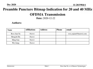
January, 2025 doc.: IEEE 802.11-25/403r0 Introduction Group has agreed to carry an intermediate FCS field in a trigger frame when one or more recipient UHR STA(s) operating in DSO, EMLSR or DPS modes require it. The I-FCS can be carried in in Trigger frames in dedicated User Info field(s) Frame Control Duration RA TA Common Info User Info List Padding FCS Special User Info Some User Info fields I-FCS Some User Info fields In this presentation, we discuss the complications in the reception process of the I-FCS and propose some solutions to address the same. Submission Slide 3 Vishnu Ratnam, Samsung Electronics
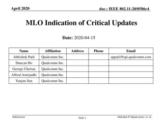
January, 2025 doc.: IEEE 802.11-25/403r0 Reception of I-FCS In some implementations early processing of frames based on I-FCS is difficult, because the PHY doesn't know how much data the MAC wants. If the MAC doesn t get enough data (that covers I-FCS), it has to ask for some more data from PHY and then either re-process from the start (wasteful/slow) or remember its parsing state (non-trivial). Without knowing how much more data to send, the MAC may get too much (causing wastage of padding), or even worse get too little and has to ask for even more iteratively. Correspondingly, to ensure that sufficient data is forwarded from PHY to the MAC that covers the I-FCS, it is helpful to either: Have a pre-deterministic location of the I-FCS, or Have an indication of the location of the I-FCS early within the trigger frame. In this contribution, we discuss a method for such I-FCS indication, and the corresponding receiver behavior. Too much data forwarded by PHY to MAC, causing wastage of padding To little data forwarded by PHY to MAC PHY Header MAC Header Common Info User Info List 1 I-FCS User Info List 2 Padding FCS Submission Slide 4 Vishnu Ratnam, Samsung Electronics
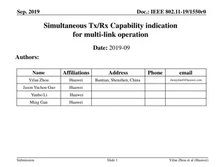
January, 2025 doc.: IEEE 802.11-25/403r0 Proposed solution Location indication: The I-FCS is carried in 2 User Info fields with AID12 = 2009. In either the Common Info field or Special User Info field (with AID12=2007) or some new User Info field (e.g. AID12=4003), within the Trigger frame, an indication of the location of I- FCS is provided. The location indication may indicate, for example, the number of octets to the end of I-FCS, or the number of User Info fields present before the I-FCS field. The I-FCS is computed based on all the bits of the Trigger frame that precede its location in the Trigger frame. Receiver behavior: At the receiving STA, the PHY is configured to provide first ? octets to the MAC, which will include the first few User Info fields of the trigger frame. From these, the STA can know if I-FCS is present and the location of the I-FCS. If I-FCS is present, the receiver s MAC configures the PHY to transmit the appropriate number of further octets to ensure I-FCS is received. Future expansion: The location indication can also be generalized to pass information to the receiver on the location of the end-of-frame-without padding, even when I-FCS is not present. Submission Slide 5 Vishnu Ratnam, Samsung Electronics
January, 2025 doc.: IEEE 802.11-25/403r0 Conclusion Having an unknown location of the I-FCS field in a trigger frame can complicate the reception process at a receiver. This can be remedied by carrying an indication of the location of the I-FCS early within the trigger frame. The length indication can also be used as a generic mechanism to pass information to the receiver. Submission Slide 6 Vishnu Ratnam, Samsung Electronics
January, 2025 doc.: IEEE 802.11-25/403r0 References 1. 2. 3. 4. 5. 6. 11-23/1873r1 Post-fcs-mac-padding 11-23/2003r1 Client-power-save 11-24/0544r1 Power-save-protocols-for-uhr-follow-up 11-24/1227r1 Some-usage-of-intermediate-fcs 11-24/1129r1 Discussion-on-intermediate-fcs-signaling 11-24/1702r0 Consideration-on-the-signalling-method-of-intermediate-fcs (Yanchao Xu, Amlogic) Submission Slide 7 Vishnu Ratnam, Samsung Electronics
January, 2025 doc.: IEEE 802.11-25/403r0 Backup slides Submission Slide 8 Vishnu Ratnam, Samsung Electronics