IEEE 802.11ax Analysis for IMT-2020 eMBB Indoor Scenarios
Explore the analysis of IEEE 802.11ax capabilities in meeting IMT-2020 requirements for eMBB Indoor scenarios. Discover potential enhancements for better alignment with specifications and standards.

Download Presentation

Please find below an Image/Link to download the presentation.
The content on the website is provided AS IS for your information and personal use only. It may not be sold, licensed, or shared on other websites without obtaining consent from the author. If you encounter any issues during the download, it is possible that the publisher has removed the file from their server.
You are allowed to download the files provided on this website for personal or commercial use, subject to the condition that they are used lawfully. All files are the property of their respective owners.
The content on the website is provided AS IS for your information and personal use only. It may not be sold, licensed, or shared on other websites without obtaining consent from the author.
E N D
Presentation Transcript
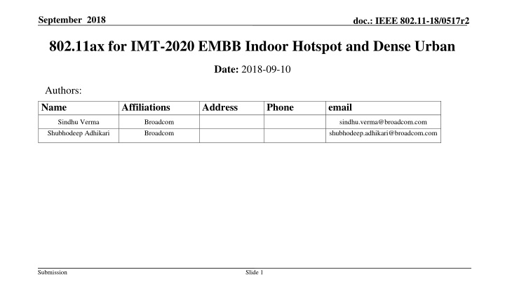
September 2018 doc.: IEEE 802.11-18/0517r2 802.11ax for IMT-2020 EMBB Indoor Hotspot and Dense Urban Date: 2018-09-10 Authors: Name Affiliations Address Phone email Sindhu Verma Shubhodeep Adhikari Broadcom Broadcom sindhu.verma@broadcom.com shubhodeep.adhikari@broadcom.com Submission Slide 1
September 2018 doc.: IEEE 802.11-18/0517r2 Abstract This presentation provides an analysis of 802.11ax capabilities vis- -vis the IMT-2020 requirements for the eMBB Indoor Hotspot and Dense Urban scenarios. It also highlights the possible enhancements that can be introduced in 802.11ax either as implementation specifics or in standards to better satisfy the requirements. Submission Slide 2
September 2018 doc.: IEEE 802.11-18/0517r2 Outline (1) The presentation discusses the following topics in the order given below. 1. Peak Spectral Efficiency a. IMT-2020 requirement for Peak Spectral Efficiency b. 802.11ax estimate for Peak Spectral Efficiency 2. Peak Data Rate a. IMT 2020 requirement for Peak Data Rate b. 802.11ax estimate for Peak Data Rate 3. 5%ile User Spectral Efficiency a. IMT 2020 requirement for 5%ile User Spectral Efficiency b. 802.11ax estimate for 5%ile DL User Spectral Efficiency in EMBB Indoor Hotspot c. 802.11ax estimate for 5%ile UL User Spectral Efficiency in EMBB Indoor Hotspot d. 802.11ax estimate for 5%ile DL User Spectral Efficiency in EMBB Dense Urban e. 802.11ax estimate for 5%ile UL User Spectral Efficiency in EMBB Dense Urban 4. 5%ile User Experienced Data Rate a. IMT 2020 requirement for 5%ile User Experienced Data Rate for EMBB Dense Urban b. 802.11ax estimate for 5%ile User Experienced Data Rate in EMBB Dense Urban Submission Slide 3
September 2018 doc.: IEEE 802.11-18/0517r2 Outline (2) 5. Average spectral efficiency a. IMT 2020 requirement for Average spectral efficiency b. IMT 2020 configuration for Average spectral efficiency: EMBB Indoor Hotspot c. 802.11ax estimate for DL Average spectral efficiency - EMBB Indoor Hotspot d. 802.11ax estimate for UL Average spectral efficiency - EMBB Indoor Hotspot e. IMT 2020 configuration for Average spectral efficiency: EMBB Dense Urban f. 802.11ax estimate for DL Average spectral efficiency - EMBB Dense Urban g. 802.11ax estimate for UL Average spectral efficiency - EMBB Dense Urban 6. Area traffic capacity a. IMT 2020 requirement for Area traffic capacity for EMBB Indoor Hotspot b. 802.11ax estimate for Area traffic capacity Data Rate in EMBB Indoor Hotspot 7. Mobility 8. References 9. Appendix Text copied from the ITU-R IMT 2020 documents [1] and [2] are marked in blue. Submission Slide 4
September 2018 doc.: IEEE 802.11-18/0517r2 Notes (1) 1. The derivations do not assume any of the following schemes (some of which are already supported in current 802.11ax devices) that can increase the realized SINR and/or the average spectral efficiency for a given geometry SINR: a. Successive Interference Cancellation b. Interference Coordination c. Adaptive FDD/TDD d. Frequency Reuse e. Improvements in device sensitivity that are be possible in the next 4-5 years f. Increasing the maximum code rate, for example for 1024 QAM from 0.83 to 0.9 and higher. However, the simulations required for IMT 2020 self evaluation should model all of the above. This will significantly improve the 802.11ax metrics. 2. For MIMO systems, the derivations only assume transmit and receive array gain and not transmit and receive diversity gain. This leads to conservative SINR and hence conservative spectral efficiency estimates. 3. The mobility model for IMT 2020 Indoor Hotspot and Dense Urban is as follows: a. Indoor Hotspot: 100% UEs at 3 kmph b. Dense Urban: 80% UEs at 3 kmph and 20% UEs at 30 kmph As a first pass estimate, the derivations assume only Doppler and no actual movement of the UEs. Actual mobility may be considered in the simulations. 4. The IMT-2020 requirements specify that the evaluations should consider the effective bandwidth, which is the operating bandwidth normalized appropriately considering the uplink/downlink ratio. So, the estimates provided in this document consider the DL and UL transmission times separately and do not consider the time required for CCA. Submission Slide 5
September 2018 doc.: IEEE 802.11-18/0517r2 IMT-2020 requirement for Peak Spectral Efficiency Definition [1]: Peak spectral efficiency is the maximum data rate under ideal conditions normalised by channel bandwidth (in bit/s/Hz), where the maximum data rate is the received data bits assuming error-free conditions assignable to a single mobile station, when all assignable radio resources for the corresponding link direction are utilized. The requirement is applicable to EMBB. Peak Spectral efficiency requirement: DL/UL: 30/15 bits/s/Hz. Evaluation Method: Analytical (via calculation or mathematical analysis). Simulations are not required for this metric. Relevant Requirement Details Notes 1 Layer 1 and Layer 2 overhead should be accounted for in time and frequency 2 For TDD, the channel bandwidth information should include the effective bandwidth, which is the operating bandwidth normalized appropriately considering the uplink/downlink ratio. As 802.11 is a TDD system, this means that while calculating the DL and UL spectral efficiency, the total bandwidth has to be scaled by the time required to transmit in the DL or UL. This would lead to a higher spectral efficiency than what is usually considered in 802.11. 3 Proponents should demonstrate that the peak spectral efficiency requirement can be met for, at least, one of the carrier frequencies assumed in the test environments under the eMBB usage scenario The carrier frequencies are 4 GHz, 30 GHz and 70 GHz and the peak spectral efficiency has to be met for at least one. So, it suffices for 802.11 to meet the target for 4 GHz. Submission Slide 6
September 2018 doc.: IEEE 802.11-18/0517r2 802.11ax estimate for Peak Spectral Efficiency Relevant Requirement Details Notes 5 Carrier Frequency 4GHz 30 GHz 70 GHz The number of allowable spatial layers is the maximum realizable under the given antenna configuration. Number of antenna elements per TRxP Up to 256 Tx/Rx Up to 256 Tx/Rx Up to 1024 Tx/Rx Number of UE antenna elements Up to 8 Tx/Rx Up to 32 Tx/Rx Up to 64 Tx/Rx Peak Spectral efficiency estimate for 802.11ax: 1. Max instantaneous PHY rate = 60 bits/s/Hz in an 8x8 configuration 2. L1/L2 overhead (max 11ax packet size, control packet excluded): a. L1 overhead = 2.06 % b. L2 overhead = 1.27% 3. Peak Spectral efficiency = max instantaneous data rate * max L1 efficiency * max L2 efficiency = 60*(1-0.0206)*(1- 0.0127) = 58.01 bits/s/Hz. 802.11ax meets the IMT-2020 EMBB peak spectral efficiency requirement with currently supported configuration Submission Slide 7
September 2018 doc.: IEEE 802.11-18/0517r2 IMT 2020 requirement for Peak Data Rate Definition [1]: Let W denote the channel bandwidth and SEp denote the peak spectral efficiency in that band. Then the user peak data rate Rp is given by: Rp = W Sep. In case bandwidth is aggregated across multiple bands, the peak data rate will be summed over the bands. Therefore, if bandwidth is aggregated across Q bands then the total peak data rate is R= i,QWi SEpi , where Wi and SEpi (i = 1, Q) are the component bandwidths and spectral efficiencies respectively. The requirement is applicable to EMBB. Peak Data rate requirement: DL/UL: 20/10 Gbps. Evaluation Method: Analytical Please note the following in addition to the notes for Peak Spectral Efficiency Notes Relevant Requirement Details 1 Peak data rate is aggregated over all operating bands This means that if an 802.11 device is able to operate simultaneously over multiple bands, the peak data rate is the sum of the data rates over each such band. Commercially available 802.11 devices already support this. So, utilizing this feature will help in meeting the requirements for this metric. Submission Slide 8
September 2018 doc.: IEEE 802.11-18/0517r2 802.11ax estimate for Peak Data Rate Peak Data rate estimate for 802.11ax: 1. Max instantaneous PHY data rate = (9.6 + 9.6 + 2.294) Gbps = 21.494 Gbps (8x8 HE 160 + HE160 + HE40) 2. L1/L2 overhead (max 11ax packet size, control packet excluded): a. L1 overhead = 2.06 % b. L2 overhead = 1.27% 3. Peak Data rate (after adding overheads) = data_rate * simultaneous operating bands * max L1 efficiency * max L2 efficiency = 21.494 *(1-0.0206)*(1-0.0127) = 20.78387 Gbps 802.11ax meets the IMT-2020 EMBB peak data rate requirement in DL and UL. Note: Future enhancements to 802.11ax to increase the peak data rate can be as follows: a. Increasing the maximum supported bandwidth b. Increasing the maximum supported spatial layers c. Increasing the maximum code rate for 1024 QAM from 0.83 to 0.9 and higher. 3GPP NR envisages a maximum code rate of 0.98. d. Supporting 4096 QAM Submission Slide 9
September 2018 doc.: IEEE 802.11-18/0517r2 IMT 2020 requirement for 5%ile User Spectral Efficiency Definition: 5th percentile user spectral efficiency is the 5th percentile point of the cumulative distribution function (CDF) of the normalized user throughput, estimated from all possible user locations. The requirement is applicable to EMBB. The requirement is as follows: 1. EMBB Indoor Hotspot: DL/UL: 0.3/0.21 bits/s/Hz a. For 20 MHz bandwidth this translates to: DL: 6 Mbps, UL = 4.2 Mbps. 2. EMBB Dense Urban: DL/UL: 0.225/0.15 bits/s/Hz a. For 20 MHz bandwidth this translates to: DL: 4.5 Mbps, UL = 3 Mbps Evaluation Method: Simulations based on the methodology specified in [2] The final technical evaluation of this metric requires simulations based on the configurations and methodology specified in [2]. For the time being, we provide estimates for 802.11ax by reusing the SINR CDF data presented in 3GPP by different companies as part of NR self evaluation towards meeting IMT 2020 requirements [3]. Submission Slide 10
September 2018 802.11ax estimate for 5%ile DL User Spectral Efficiency in EMBB Indoor Hotspot doc.: IEEE 802.11-18/0517r2 The CDF of the normalized user throughput depends on the following: 1. CDF of the geometry SINR 2. Number of users per TRxP 3. Mapping between the geometry SINR and the realized SINR. So, techniques that can increase the realized SINR and/or the average spectral efficiency for the given geometry SINR will also increase the 5%ile spectral efficiency. The geometry SINR CDF is the mean of evaluations submitted in 3GPP by various companies [3] 5%ile DL geometry SINR = -3.3 dB UE density: 10 UEs per TRxP Antenna configuration: ENB: 32Tx/Rx, UE: 4Tx/Rx It can be expected that with similar transmit power and transmission schemes, 802.11ax geometry SINR CDF will be similar. Submission Slide 11
September 2018 doc.: IEEE 802.11-18/0517r2 802.11ax estimate for 5%ile DL User Spectral Efficiency in EMBB Indoor Hotspot We provide 802.11ax estimates by assuming the following: Average MU-MIMO factor = 4 (feasible given the 32 Tx/Rx antenna configuration at the ENB/AP), Average transmission rank per UE = 2 Frequency Selective Multi-User scheduling gain = 3 dB Transmit array gain = 6 dB (8 Tx antennas per DL MU-MIMO user with rank 2) Receive array gain = 3 dB (4 Rx antennas per rank 2 user) 10% PER Given the above: Effective 5%ile DL SINR = 8.7 dB (geometry SINR + 12 dB) 5%ile DL SINR per stream over each of the 8 spatial streams (2 spatial streams for 4 MU-MIMO users) = -0.3 dB 5%ile DL MCS supported over each spatial stream = 0 (Data rate of 8.6 Mbps for 20 MHz) Configuration 1: Assuming max 802.11ax packet size, control packet excluded: L1 overhead ~ 0 % (The packet duration is very high compared to the L1 overhead) L2 overhead = 1.27% 802.11ax 5%ile Downlink user spectral efficiency = data rate * transmission rank * MU-MIMO factor * (1/bandwidth)* L1 efficiency * L2 efficiency * (1-PER) = (8.6 )*(2)*(4 /10)*(1/20) *(1-0.0127)*1*0.9 bits/s/Hz = 0.31 bits/s/Hz Submission Slide 12
September 2018 doc.: IEEE 802.11-18/0517r2 802.11ax estimate for 5%ile DL User Spectral Efficiency in EMBB Indoor Hotspot Configuration 2: Assuming max packet duration of 10 ms, control packet excluded: L1 overhead = 0.44 % L2 overhead = 1.43 % 802.11ax 5%ile Downlink user spectral efficiency = data rate * transmission rank * MU-MIMO factor * L1 efficiency * L2 efficiency * (1-PER) * (1/bandwidth) = (8.6 )*(2)*(4 /10)*(1/20) *(1-0.0143)*(1-0.0044)*0.9 bits/s/Hz = 0.30 bits/s/Hz 802.11ax DL is expected to meet the requirement for IMT-2020 EMBB Indoor Hotspot 5%ile User Spectral Efficiency. However, since the requirement is met with a thin margin, we should investigate means of increasing the spectral efficiency, along the lines of those described in the slide Notes (1). Submission Slide 13
September 2018 doc.: IEEE 802.11-18/0517r2 802.11ax estimate for 5%ile UL User Spectral Efficiency in EMBB Indoor Hotspot The SINR CDF is the mean of evaluations submitted in 3GPP by various companies [3] UL Max Tx power is lower than DL Max Tx power by 1 dB (Tx power difference) BS noise figure is 2 dB lower than UE noise figure Approximate UL geometry SINR for a UE = DL SINR + 1 dB 5%ile UL geometry SINR = -2.3 dB It can be expected that with similar transmit power and transmission schemes, 802.11ax geometry SINR CDF can be similar. Submission Slide 14
September 2018 doc.: IEEE 802.11-18/0517r2 802.11ax estimate for 5%ile UL User Spectral Efficiency in EMBB Indoor Hotspot We provide 802.11ax estimates by assuming the following: Average MU-MIMO factor = 4 ( feasible with the given antenna configuration), Average transmission rank per UE = 2 Frequency Selective Multi-User scheduling gain of about 3 dB Transmit array gain = 3 dB (4 Tx antennas per UL MU-MIMO user with rank 2) Receive array gain = 6 dB (32 Rx antennas for 8 streams) 10% PER Given the above: Effective 5%ile UL SINR = 9.7 dB 5%ile UL SINR per stream over each of the 8 spatial streams (2 spatial streams for 4 MU-MIMO users) =6.7 dB (Tx power can be max for each of the UL MU-MIMO users) 5%ile UL MCS supported over each spatial stream = 2 ( Data rate of 25.8 Mbps for 20 MHz) Configuration 1: Assuming max 802.11ax packet size, control packet excluded: L1 overhead ~0 % L2 Overhead = 1.27% 802.11ax 5%ile Uplink user spectral efficiency = (25.8 )*(2)*(4 /10)*(1/20)*(1-0.0127)*0.9 bits/s/Hz = 0.92 bits/s/Hz Submission Slide 15
September 2018 802.11ax estimate for 5%ile UL User Spectral Efficiency in EMBB Indoor Hotspot doc.: IEEE 802.11-18/0517r2 Configuration 2: Assuming max packet duration of 10ms, control packet excluded: L1 overhead = 0.44 % L2 Overhead = 1.26 % 802.11ax 5%ile Uplink user spectral efficiency = (25.8 )*(2)*(4 /10)*(1/20)*(1-0.0126)*(1-0.0044)*0.9 bits/s/Hz = 0.91 bits/s/Hz 802.11ax UL is expected to meet the requirement for IMT-2020 EMBB Indoor Hotspot 5%ile User Spectral Efficiency Submission Slide 16
September 2018 doc.: IEEE 802.11-18/0517r2 802.11ax estimate for 5%ile DL User Spectral Efficiency in EMBB Dense Urban The final technical evaluation of this metric requires simulations based on the configurations and methodology specified in [2]. However, for the time being, we provide estimates for 802.11ax by reusing SINR CDF data presented in 3GPP by different companies as part of NR self evaluation towards meeting IMT 2020 requirements [3]. The geometry SINR CDF is the mean of evaluations submitted in 3GPP by various companies [3] 5%ile DL geometry SINR = 2.5 dB UE density: 10 UEs per TRxP Antenna configuration: ENB: 128Tx/Rx UE: 4Tx/Rx It can be expected that with similar transmit power and transmission schemes, 802.11ax geometry SINR CDF can be similar. Submission Slide 17
September 2018 doc.: IEEE 802.11-18/0517r2 802.11ax estimate for 5%ile DL User Spectral Efficiency in EMBB Dense Urban We provide 802.11ax estimates by assuming the following: Average MU-MIMO factor = 4. Note: The 128 Tx/Rx configuration at the ENB should support a MU-MIMO factor higher than 4. However, we still assume 4 as it is possible to meet the IMT 2020 requirements with this. Average transmission rank per UE = 2 Frequency Selective Multi-User scheduling gain of about 3 dB Transmit array gain = 12 dB (128 Tx antennas per DL MU-MIMO user with rank 2) Receive array gain = 3 dB (4 Rx antennas for 2 streams) 10% PER Given the above: Effective 5%ile DL SINR = 20.5 dB 5%ile DL SINR per stream over each of the 8 spatial streams (2 spatial streams for 4 MU-MIMO users) = 11.5 dB 5%ile DL MCS supported over each spatial stream = 3 (Data rate of 34.4 Mbps for 20 MHz) Configuration 1: Assuming max 802.11ax packet size, control packet excluded: L1 overhead ~0 % L2 Overhead = 1.27% 802.11ax 5%ile Uplink user spectral efficiency = (34.4)*(2)*(4 /10)*(1/20) *(1-0.0127)*0.9 bits/s/Hz = 1.22 bits/s/Hz Submission Slide 18
September 2018 doc.: IEEE 802.11-18/0517r2 802.11ax estimate for 5%ile DL User Spectral Efficiency in EMBB Dense Urban Configuration 2: Assuming max packet duration of 10 ms, control packet excluded: L1 overhead = 0.44 % L2 Overhead = 1.3 % 5%ile Uplink user spectral efficiency = (34.4)*(2)*(4 /10)*(1/20)*(1-0.013)*(1-0.0044)*0.9 bits/s/Hz = 1.22 bits/s/Hz 802.11ax DL is expected to meet the requirement for IMT-2020 EMBB Dense Urban 5%ile User Spectral Efficiency Submission Slide 19
September 2018 doc.: IEEE 802.11-18/0517r2 802.11ax estimate for 5%ile UL User Spectral Efficiency in EMBB Dense Urban The DL geometry SINR CDF is the mean of evaluations submitted in 3GPP by various companies [3] UL Max Tx power is lower than DL Max Tx power by 21 dB ( Tx power difference) BS noise figure is 2 dB lower than UE noise figure Approximate UL geometry SINR for a UE = DL SINR - 19 dB 5%ile UL geometry SINR = -16.5 dB With similar transmit power and transmission schemes, 802.11ax geometry SINR CDF can be similar. Submission Slide 20
September 2018 doc.: IEEE 802.11-18/0517r2 802.11ax estimate for 5%ile UL User Spectral Efficiency in EMBB Dense Urban We provide 802.11ax estimates by assuming the following: Average MU-MIMO factor = 4 ( feasible with the given antenna configuration), Average transmission rank per UE =1 Frequency Selective Multi-User scheduling gain of about 3 dB Transmit array gain = 6 dB (4 Tx antennas per UL MU-MIMO user with rank 1) Receive array gain = 15 dB (128 Rx antennas for 4 streams) 10% PER Given the above: Effective 5%ile UL SINR = 7.5 dB 5%ile UL SINR per stream over each of the 4 spatial streams (1 spatial stream for 4 MU-MIMO users) = 7.5 dB (Tx power can be max for each of the UL MU-MIMO users) 5%ile UL MCS supported over each spatial stream = 2 (Data rate of 25.8 Mbps for 20 MHz) Configuration 1: Assuming max 802.11ax packet size, control packet excluded: L1 overhead ~0 % L2 Overhead = 1.27% 802.11ax 5%ile Uplink user spectral efficiency = (25.8 )*(1)*(4 /10)*(1/20) *(1-0.0127)*0.9 bits/s/Hz = 0.46 bits/s/Hz Submission Slide 21
September 2018 doc.: IEEE 802.11-18/0517r2 802.11ax estimate for 5%ile UL User Spectral Efficiency in EMBB Dense Urban Configuration 2: Assuming max 802.11ax packet size, control packet excluded: L1 overhead = 0.4 % L2 Overhead = 1.26 % 802.11ax 5%ile Uplink user spectral efficiency = (25.8 )*(1)*(4 /10)*(1/20) *(1-0.0126)*(1-0.004)*0.9 bits/s/Hz = 0.46 bits/s/Hz 802.11ax UL is expected to meet the requirement for IMT-2020 EMBB Dense Urban 5%ile User Spectral Efficiency Submission Slide 22
September 2018 doc.: IEEE 802.11-18/0517r2 IMT 2020 requirement for 5%ile User Experienced Data Rate Definition: User experienced data rate is the 5% point of the cumulative distribution function (CDF) of the user throughput. User throughput (during active time) is defined as the number of correctly received bits, i.e. the number of bits contained in the service data units (SDUs) delivered to Layer 3, over a certain period of time. In case of one frequency band and one layer of transmission reception points (TRxP), the user experienced data rate could be derived from the 5th percentile user spectral efficiency. Let W denote the channel bandwidth and SEuser denote the 5th percentile user spectral efficiency. Then the user experienced data rate, Ruser is given by: Ruser = W SEuser. If the bandwidth is aggregated across multiple bands (one or more TRxP layers), the user experienced data rate is summed over the bands. The requirement is applicable to EMBB Dense Urban.DL 100 Mbit/s. UL 50 Mbit/s. Submission Slide 23
September 2018 doc.: IEEE 802.11-18/0517r2 802.11ax estimate for 5%ile User Experienced Data Rate in EMBB Dense Urban From the estimated 5%ile spectral efficiency for Configuration 1: Assuming max 11ax packet size, control packet excluded: DL user experienced data rate = 1.22 bits/s/Hz * 160 MHz = 195.2 Mbps UL user experienced data rate = 0.46 bits/s/Hz * 160 MHz = 73.6 Mbps 802.11ax should meet the requirement for IMT-2020 EMBB Dense Urban 5%ile User Experienced Data Rate Note: The 3GPP geometry SINR is plotted over 20 MHz. In the above, we have multiplied the 5% spectral efficiency at the corresponding SINR with 160 MHz bandwidth. Since the device transmit power may not scale with bandwidth, it is not necessary that the same SINR CDF is achievable for transmission over 160 MHz bandwidth. However, both signal and interference PSD can reduce with bandwidth and hence, the final SINR may be equivalent. Submission Slide 24
September 2018 doc.: IEEE 802.11-18/0517r2 IMT 2020 requirement for Average spectral efficiency Definition: Let Ri (T) denote the number of correctly received bits by user i (i = 1, N) (downlink) or from user i (uplink) in a system comprising a user population of N users and M Transmission Reception Points (TRxPs). Let W denote the channel bandwidth and T the time over which the data bits are received. The average spectral efficiency may be estimated by running system-level simulations over number of drops Ndrops. Each drop gives a value of denoted as: and the estimated average spectral efficiency resulting is given by: For TDD, the channel bandwidth information should include the effective bandwidth, which is the operating bandwidth normalized appropriately considering the uplink/downlink ratio. Evaluation Method: Simulations based on the methodology specified in [2]. Requirement: 1. EMBB Indoor Hotpot: DL/UL = 9/6.75 bits/s/Hz/TRxP 2. EMBB Dense Urban: DL/UL: 7.8/5.4 bits/s/Hz/TRxP Submission Slide 25
September 2018 doc.: IEEE 802.11-18/0517r2 IMT 2020 configuration for Average spectral efficiency: EMBB Indoor Hotspot IMT 2020 Indoor Hotspot Configuration A 11ax Residential 11ax Enterprise 4 GHz 2.4 GHz, 5 GHz 2.4 GHz, 5 GHz Carrier Frequency ISD 20 m 10 m 20 m Total transmit power per TRxP 24 dBm for 20 MHz bandwidth UE Tx power 23 dBm 15 dBm/antenna 15 dBm/antenna Number of antenna elements per TRxP Up to 256 Tx/Rx 4 Tx/Rx 4 Tx/Rx Number of UE antenna elements Up to 8 Tx/Rx 2 Tx/Rx 2 Tx/Rx BS NF 5 dB 7 dB 7 dB BS antenna element gain 5 dBi 0 dBi 0 dBi UE antenna element gain 0 dBi -2 dBi -2 dBi UE speed 3 Kmph 0.089 Kmph 0.089 Kmph Submission Slide 26
September 2018 802.11ax estimate for DL Average spectral efficiency - EMBB Indoor Hotspot doc.: IEEE 802.11-18/0517r2 The final technical evaluation of this metric requires simulations based on the configurations and methodology specified in [2]. However, for the time being, we provide estimates for 802.11ax by reusing SINR CDF data presented in 3GPP by different companies as part of NR self evaluation towards meeting IMT 2020 requirements [3]. The geometry SINR CDF is the mean of evaluations submitted in 3GPP by various companies [3] UE density: 10 UEs per TRxP Antenna configuration: ENB: 32Tx/Rx UE: 4Tx/Rx It can be expected that with similar transmit power and transmission schemes, 802.11ax geometry SINR CDF can be similar. Submission Slide 27
September 2018 802.11ax estimate for DL Average spectral efficiency - EMBB Indoor Hotspot doc.: IEEE 802.11-18/0517r2 We provide 802.11ax estimates by assuming the following: Average MU-MIMO factor = 4 ( feasible with the given antenna configuration), Assume average transmission rank per UE = 2 Assume a Frequency Selective Multi-User scheduling gain of about 3 dB Transmit array gain = 6 dB (8 tx antennas per DL MU-MIMO user with rank 2) Receive array gain = 3 dB (4 rx antennas per rank 2 user) DL SINR per stream over each of the 8 spatial streams (2 spatial streams for 4 MU-MIMO users) is 3 dB better than the curve shown Average DL data rate supported over each spatial stream and over each user for 20 MHz and 1 TRxP = 25 Mbps 10% PER Configuration 1: Assuming max 802.11ax packet size, control packet excluded: L1 overhead ~ 0 % L2 Overhead = 1.27 % 802.11ax Average Downlink user spectral efficiency = (25 )*(2)*(4)*(1/20)*(1-0.0127)*0.9 bits/s/Hz = 8.88 bits/s/Hz/TRxP Submission Slide 28
September 2018 802.11ax estimate for DL Average spectral efficiency - EMBB Indoor Hotspot doc.: IEEE 802.11-18/0517r2 Configuration 2: Assuming max packet duration of 10 ms, control packet excluded: L1 overhead = 0.44% L2 Overhead ~1.3 % 802.11ax Average Downlink user spectral efficiency = (25 )*(2)*(4)*(1/20)*(1-0.013)*(1-0.0044) bits/s/Hz = 8.84 bits/s/Hz/TRxP Under the assumptions on the previous slides, the estimated spectral efficiency of 802.11ax (8.84) would not meet the requirement for IMT-2020 EMBB Indoor Hotspot (9). However, please note the following: 1. By utilizing the schemes mentioned in Notes(1), it is possible to improve the spectral efficiency and meet the requirement. 2. It is also possible to meet the requirements by modifying some of the assumptions made in the estimate, for example: a. Considering transmit and receive diversity gain b. Higher average MU-MIMO factor and/or rank. Simulations are required to quantify the gains by these schemes. Submission Slide 29
September 2018 802.11ax estimate for UL Average spectral efficiency - EMBB Indoor Hotspot doc.: IEEE 802.11-18/0517r2 Effectively, UL Max Tx power is lower than DL Max Tx power by 1 dB (Tx power difference) BS noise figure is 2 dB lower than UE noise figure Approximate UL geometry SINR for a UE = corresponding DL SINR + 1 dB UE density: 10 UEs per TRxP Antenna configuration: 32Tx/Rx at ENB, 4 TX/RX at UE Assume an average MU-MIMO factor = 4 ( feasible with the given antenna configuration), Assume average transmission rank per UE = 2 Assume a Frequency Selective Multi-User scheduling gain of about 3 dB Transmit array gain = 3 dB (4 tx antennas per UL MU-MIMO user with rank 2) Receive array gain = 6 dB (32 rx antennas for 8 streams) Effective UL SINR per stream over each of the 8 spatial streams (2 spatial streams for 4 MU-MIMO users) is 10 dB better than the curve shown (Tx power can be max for each of the UL MU-MIMO users) Average UL data rate supported over each spatial stream and over each user for 20 MHz and 1 TRxP = 48.11 Mbps 10% PER Configuration 1: Assuming max 802.11ax packet size, control packet excluded: L1 overhead ~0 % L2 Overhead = 1.27 % 802.11ax Average Uplink user spectral efficiency = (48.11 )*(2)*(4)*(1/20) *(1-0.0127)*0.9 bits/s/Hz = 17.1 bits/s/Hz/TRxP Submission Slide 30
September 2018 802.11ax estimate for UL Average spectral efficiency - EMBB Indoor Hotspot doc.: IEEE 802.11-18/0517r2 Configuration 2: Assuming max packet duration of 10ms, control packet excluded: L1 overhead = 0.44% L2 Overhead ~1.3 % 802.11ax Average Uplink user spectral efficiency = (48.11 )*(2)*(4)*(1/20) *(1-0.013)*(1-0.0044)*0.9 bits/s/Hz = 17.02 bits/s/Hz/TRxP 802.11ax UL is expected to meet the requirement for IMT-2020 EMBB Indoor Hotspot Average Spectral Efficiency Submission Slide 31
September 2018 doc.: IEEE 802.11-18/0517r2 IMT 2020 configuration for Average spectral efficiency: EMBB Dense Urban Dense Urban Configuration A 11ax Outdoor Large BSSl 4 GHz 2.4 GHz, 5 GHz Carrier Frequency ISD 200 m 130 m BS antenna height 25 m 10 m Total transmit power per TRxP 41/44 dBm for 10/20 MHz 20 dBm per AP UE Tx power 23 dBm 15 dBm per client Number of antenna elements per TRxP Up to 256 Tx/Rx 4 Tx/Rx Number of UE antenna elements Up to 8 Tx/Rx 2 Tx/Rx BS NF 5 dB 7 dB BS antenna element gain 8 dBi 0 dBi UE antenna element gain 0 dBi -2 dBi UE speed Indoor: 3 kmph, Outdoor: 30 Kmph Submission Slide 32
September 2018 802.11ax estimate for DL Average spectral efficiency - EMBB Dense Urban doc.: IEEE 802.11-18/0517r2 The final technical evaluation of this metric requires simulations based on the configurations and methodology specified in [2]. However, for the time being, we provide estimates for 802.11ax by reusing SINR CDF data presented in 3GPP by different companies as part of NR self evaluation towards meeting IMT 2020 requirements [3]. The geometry SINR CDF is the mean of evaluations submitted in 3GPP by various companies [3] UE density: 10 UEs per TRxP Antenna configuration: END: 128 Tx/Rx UE: 4Tx/Rx It can be expected that with similar transmit power and transmission schemes, 802.11ax geometry SINR CDF can be similar. Submission Slide 33
September 2018 doc.: IEEE 802.11-18/0517r2 802.11ax estimate for DL Average spectral efficiency - EMBB Dense Urban Assume an average MU-MIMO factor = 4 ( feasible with the given antenna configuration), Assume average transmission rank per UE = 2 Assume a Frequency Selective Multi-User scheduling gain of about 3 dB Transmit array gain = 12 dB (32 tx antennas per DL MU-MIMO user with rank 2) Receive array gain = 3 dB (4 rx antennas per rank 2 user) DL SINR per stream over each of the 8 spatial streams (2 spatial streams for 4 MU-MIMO users) is 9 dB better than the curve shown Average DL data rate supported over each spatial stream and over each user for 20 MHz and 3 TRxPs = 96.18 Mbps 10% PER Configuration 1: Assuming max 802.11ax packet size, control packet excluded: L1 overhead ~0 % L2 Overhead = 1.27 % 802.11ax Average Downlink user spectral efficiency = (96.18)*(2)*(4)*(1/20)*(1/3)*(1-0.0127)*0.9 bits/s/Hz = 11.4 bits/s/Hz/TRxP Configuration 2: Assuming max packet duration of 10 ms, control packet excluded: L1 overhead = 0.44% L2 Overhead ~ 1.3 % 802.11ax Average Downlink user spectral efficiency = (96.18)*(2)*(4)*(1/20)*(1/3)*(1-0.013)*(1-0.0044)*0.9 bits/s/Hz = 11.34 bits/s/Hz/TRxP 802.11ax DL is expected to meet the requirement for IMT-2020 EMBB Dense Urban Average Spectral Efficiency Submission Slide 34
September 2018 doc.: IEEE 802.11-18/0517r2 802.11ax estimate for UL Average spectral efficiency - EMBB Dense Urban Effectively, UL Max Tx power is lower than DL Max Tx power by 21 dB (Tx power difference) BS noise figure is 2 dB lower than UE noise figure Approximate UL geometry SINR for a UE = corresponding DL SINR - 19 dB UE density: 10 UEs per TRxP Antenna configuration: 128 Tx/Rx at ENB, 4 TX/RX at UE Assume an average MU-MIMO factor = 4 ( feasible with the given antenna configuration), Assume average transmission rank per UE = 2 Assume a Frequency Selective Multi-User scheduling gain of about 3 dB Transmit array gain = 3 dB (4 Tx antennas per UL MU-MIMO user with rank 2) Receive array gain = 12 dB (128 Rx antennas for 8 streams) Effective UL SINR per stream over each of the 8 spatial streams (2 spatial streams for 4 MU-MIMO users) is 4 dB worse than the curve shown (Tx power can be max for each of the UL MU-MIMO users) Average UL data rate supported over each spatial stream and over each user for 20 MHz and 3 TRxPs = Mbps 10% PER Configuration 1: Assuming max 802.11ax packet size, control packet excluded: L1 overhead ~0 % L2 Overhead = 1.27 % 802.11ax Average Uplink user spectral efficiency = (45.37 )*(2)*(4)*(1/20)*(1/3)*(1-0.0127)*0.9 bits/s/Hz = 5.37 bits/s/Hz/TRxP Submission Slide 35
September 2018 doc.: IEEE 802.11-18/0517r2 802.11ax estimate for UL Average spectral efficiency - EMBB Dense Urban Configuration 2: Assuming max 802.11ax packet size, control packet excluded: L1 overhead = 0.44% L2 Overhead ~ 1.3 % 802.11ax Average Uplink user spectral efficiency = (45.37 )*(2)*(4)*(1/20)*(1/3)*(1-0.013)*(1-0.0044)*0.9 bits/s/Hz = 5.35 bits/s/Hz/TRxP Under the assumptions in the previous slide, the estimated UL average spectral efficiency for EMBB Dense Urban (5.37, 5.35) fails to meet the corresponding requirement (5.4) by a small margin. However, please note the following: 1. By utilizing the schemes mentioned in Notes(1), it is possible to improve the spectral efficiency and meet the requirement. 2. It is also possible to meet the requirements by modifying some of the assumptions made in the estimate, for example: a. Considering transmit and receive diversity gain b. Higher average MU-MIMO factor and/or rank. Simulations are required to quantify the gains by these schemes. Submission Slide 36
September 2018 doc.: IEEE 802.11-18/0517r2 IMT 2020 requirement for Area traffic capacity Definition: Area traffic capacity is the total traffic throughput served per geographic area (in Mbit/s/m2). The throughput is the number of correctly received bits, i.e. the number of bits contained in the SDUs delivered to Layer 3, over a certain period of time. This can be derived for a particular use case (or deployment scenario) of one frequency band and one TRxP layer, based on the achievable average spectral efficiency, network deployment (e.g., TRxP (site) density) and bandwidth. Let W denote the channel bandwidth and the TRxP density (TRxP/m2). The area traffic capacity Careais related to average spectral efficiency SEavgthrough equation Carea= W SEavg In case bandwidth is aggregated across multiple bands, the area traffic capacity will be summed over the bands. The requirement is applicable to EMBB Indoor Hotspot DL : Requirement: 10 Mbit/s/m2 Evaluation Method: Simulations based on the methodology specified in [2] Submission Slide 37
September 2018 doc.: IEEE 802.11-18/0517r2 802.11ax estimate for Area Traffic Capacity in EMBB Indoor Hotspot From the 802.11ax average spectral efficiency estimate: Average DL spectral efficiency = 8.88 bits/s/Hz Average UL spectral efficiency = 17.1 bits/s/Hz From the eMBB Indoor Hotspot topology: Area of each site = 500 m2 For 1 TRxP/site, = 1/500 = 0.002 TRxP/m2 DL Area traffic capacity = 0.0176*W Mbps/m2 UL Area traffic capacity = 0.0344*W Mbps/m2 The bandwidth should be at least 568 MHz for DL and 291 MHz for UL to satisfy the area traffic capacity of 10 Mbps/m2 The high bandwidth requirement at the same spectral efficiency is also recognised in 3GPP submissions for NR [4] Submission Slide 38
References September 2018 doc.: IEEE 802.11-18/0517r2 [1] Report ITU-R M.2410-0 (11/2017), Minimum requirements related to technical performance for IMT-2020 radio interface(s) [2] Report ITU-R M.2412-0 (10/2017), Guidelines for evaluation of radio interface technologies for IMT-2020 [3] 3GPP RT-170019, Summary of email discussion [ITU-R AH 01] Calibration for self-evaluation , 3GPP TSG RAN ITU-R ad hoc, Huawei, December 2017 [4] R1-181802435, On the IMT-2020 Self-Evaluation Performance metrics and Evaluation, Intel February, 2018 Submission Slide 39
September 2018 doc.: IEEE 802.11-18/0517r2 Appendix Submission Slide 40
802.11ax: L1/L2 Overheads (1) September 2018 doc.: IEEE 802.11-18/0517r2 L1 (MAC layer overheads) MAC layer frame overheads AMSDU subframe header (14 bytes per MSDU) AMPDU delimiter (4 bytes per MPDU) MAC/encryption header MAC layer medium exchange overhead (We can ignore these for the purpose of throughput calculations as they are also determined by licensed/unlicensed spectrum designation as well as ACK policy) Random Backoff Acknowledgement frames Protection mechanism (RTS/CTS) L1 (PHY layer overheads) STFs , LTFs, SIG fields Submission Slide 41
802.11ax: L1/L2 Overheads (2) September 2018 doc.: IEEE 802.11-18/0517r2 Sample L2 overhead calculation: Following calculation assumes MSDU size of 1500 bytes 11ax Comments 2(20+2)-1 Max A-MPDU size 256 Max aggregatable MPDU 2760 Max aggregatable MSDUs 38640 MSDU overhead (Sub Frame header) 13824 MPDU overhead (MAC Header + Crypto Header + AMPDU delimiter + FCS) 1.27% Total L2 overhead Submission Slide 42
802.11ax: L1/L2 Overheads (3) September 2018 doc.: IEEE 802.11-18/0517r2 Sample L1 overhead calculation: 11ax Comments 130,666.67 Bits/Sym (mcs11 1024 QAM code rate 160Mhz) 9607.843137 Data Rate (without overheads) (mcs11 1024 QAM code rate 160Mhz 8x8) Symbol time=13.6 us. 2(20+2)-1 Max A-MPDU size=PHY Payload size (bytes) 257 Number of data symbol with SGI=0.8us. 68 PHY header overhead (us) 3563.2 Total Packet time 9412.806466 Effective Data rate (after including L1 overheads) Total L1 % overhead 2.06% Submission Slide 43
802.11ax: L1/L2 Overheads (4) September 2018 doc.: IEEE 802.11-18/0517r2 Possible L2 Optimizations: Reducing SubFrame header from 14 bytes to 4 bytes If all frames are destined to same address, in typical use case DA/SA can be extracted from MAC header 4 bytes SFH contains length, CRC and unique identifier Submission Slide 44


")
")
")
")