IEEE 802.15.3e OOK PHY Proposal for High-Rate Close Proximity System
Explore the detailed proposal for the OOK PHY part of the IEEE 802.15.3e standard aimed at High-Rate Close Proximity Systems. The submission, prepared by a collaboration of various contributors from notable companies, focuses on the simplicity and power efficiency of On-Off Keying modulation in low-end devices. Learn about the key features, including support for channel bonding and high throughput, without the need for complex ADC/DAC considerations or MIMO technology.
Download Presentation

Please find below an Image/Link to download the presentation.
The content on the website is provided AS IS for your information and personal use only. It may not be sold, licensed, or shared on other websites without obtaining consent from the author. If you encounter any issues during the download, it is possible that the publisher has removed the file from their server.
You are allowed to download the files provided on this website for personal or commercial use, subject to the condition that they are used lawfully. All files are the property of their respective owners.
The content on the website is provided AS IS for your information and personal use only. It may not be sold, licensed, or shared on other websites without obtaining consent from the author.
E N D
Presentation Transcript
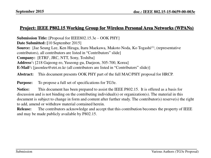
September 2015 doc.: IEEE 802.15-15-0659-00-003e Project: IEEE P802.15 Working Group for Wireless Personal Area Networks (WPANs) Submission Title: [Proposal for IEEE802.15.3e OOK PHY] Date Submitted: [10 September 2015] Source: [Jae Seung Lee, Ken Hiraga, Itaru Maekawa, Makoto Noda, Ko Togashi(1), (representative contributors), all contributors are listed in Contributors slide] Company: [ETRI1, JRC, NTT, Sony, Toshiba] Address1: [218 Gajeong-ro, Yuseong-gu, Daejeon, 305-700, Korea] E-Mail1: [jasonlee@etri.re.kr (all contributors are listed in Contributors slide)] Abstract: This document presents OOK PHY part of the full MAC/PHY proposal for HRCP. Purpose: Notice: discussion and is not binding on the contributing individual(s) or organization(s). The material in this document is subject to change in form and content after further study. The contributor(s) reserve(s) the right to add, amend or withdraw material contained herein. Release: The contributors acknowledge and accept that this contribution becomes the property of IEEE and may be made publicly available by P802.15. To propose a full set of specifications for TG3e. This document has been prepared to assist the IEEE P802.15. It is offered as a basis for Submission Various Authors (TG3e Proposal)
September 2015 doc.: IEEE 802.15-15-0659-00-003e Contributors Name Affiliation Email Jae Seung Lee ETRI jasonlee@etri.re.kr Moon-Sik Lee ETRI moonsiklee@etri.re.kr Itaru Maekawa Japan Radio Corporation maekawa.itaru@jrc.co.jp Lee Doohwan NTT Corporation lee.doohwan@lab.ntt.co.jp Ken Hiraga NTT Corporation hiraga.ken@lab.ntt.co.jp Masashi Shimizu NTT Corporation masashi.shimizu@upr-net.co.jp Keitarou Kondou Sony Corporation Keitarou.Kondou@jp.sony.com Hiroyuki Matsumura Sony Corporation Hiroyuki.Matsumura@jp.sony.com Makoto Noda Sony Corporation MakotoB.Noda at jp.sony.com Masashi Shinagawa Sony Corporation Masashi.Shinagawa@jp.sony.com Ko Togashi Toshiba Corporation ko.togashi@toshiba.co.jp Kiyoshi Toshimitsu Toshiba Corporation kiyoshi.toshimitsu@toshiba.co.jp Submission Slide 2 Various Authors (TG3e Proposal)
September 2015 doc.: IEEE 802.15-15-0659-00-003e Proposal for IEEE802.15.3e High-Rate Close Proximity System (Presentation on OOK PHY Part) September 10, 2015 Submission Slide 3 Various Authors (TG3e Proposal)
September 2015 doc.: IEEE 802.15-15-0659-00-003e Overview OOK PHY part of the Full MAC/PHY Proposal for HRCP HRCP PHY for cost effective devices (low power, low complexity) HRCP-OOK PHY OOK has been already adopted in 15.3c for low complexity and low power consumption Low complexity: OOK is the simplest modulation scheme suitable for low-end devices Low power: Transmit power can be saved since NO carrier when the device wants to send a 0 The basic design of 15.3c OOK PHY is inherited and simplified Additional support of channel bonding for higher throughput Submission Slide 4 Various Authors (TG3e Proposal)
September 2015 doc.: IEEE 802.15-15-0659-00-003e HRCP-OOK PHY Features (1/2) Low complexity, simple design Single modulation scheme: OOK Single FEC is used: RS (240, 224) Channel Bonding for High throughput Up to 4 Channels 4 channel bonding is necessary to achieve high throughput Channel bonding is easier than channel aggregation for OOK No ADC/DAC issues in OOK MIMO is not used We proposed a simple 2X2 MIMO scheme using polarization separation in July meeting, but it has been removed For low complexity and simple design Submission Slide 5 Various Authors (TG3e Proposal)
September 2015 doc.: IEEE 802.15-15-0659-00-003e HRCP-OOK PHY Features (2/2) OOK enables simplest Radio Architecture OOK device: Much simpler than FSK/PSK devices OOK vs. FSK/PSK Submission Slide 6 Various Authors (TG3e Proposal)
September 2015 doc.: IEEE 802.15-15-0659-00-003e Channel Bonding (1/2) Ch2 is the default channel (specified in TGD) Ch2 and Ch3 are used for 2 channel bonding (specified in TGD): Japan, Europe, US/Canada, South Korea, China Ch2 should be always included in the bonded channel (default channel) Only channel 2 is used for single channel transmission Since the range of Close Proximity Peer Network is very limited, the channel can be assumed to be always available Ch1, Ch2, and Ch3 are used for 3 channel bonding (Japan, Europe, US/Canada, Korea) 4 channel bonding: Japan, Europe, and South Korea Channel 1 Channel 2 Channel 3 Channel 4 Japan (57.00 - 66.00 GHz) Europe (57.00 - 66.00 GHz) U.S. and Canada (57.05 - 64.00 GHz) South Korea (57.00 -66.00 GHz) China (59.00 - 64.00 GHz) Australia (59.40 - 62.90 GHz) 57.00 57.24 58.32 59.40 60.48 61.56 62.64 63.72 64.80 65.8866.00 Submission Slide 7 Various Authors (TG3e Proposal) Frequency[GHz]
September 2015 doc.: IEEE 802.15-15-0659-00-003e Channel Bonding (2/2) HRCP PHY Channel numbering CHNL_INDEX Start frequency Center frequency Stop frequency Remarks 1 59.400 GHz 60.480 GHz 61.560 GHz No channel bonding (Use only Channel 2 - the default channel) 2 59.400 GHz 61.560 GHz 63.720 GHz Two channel bonding (Channel 2 and Channel 3) Three channel bonding (Channel 1, 2 and 3) 57.240 GHz 60.480 GHz 63.720 GHz 3 57.240 GHz 61.560 GHz 65.880 GHz Four channel bonding (Channel 1,2,3 and 4) 4 Submission Slide 8 Various Authors (TG3e Proposal)
September 2015 doc.: IEEE 802.15-15-0659-00-003e HRCP-OOK PHY frame format (1/3) - PHY frame format is similar to 15.3c OOK PHY last over air first over air PHY Payload field PHY Payload field Frame Header Frame Header PHY Preamble PHY Preamble Base frame header Base frame header Base HCS RS parity MAC PHY RS parity bits bits Base HCS MAC header header PHY header header - Preamble Structure (single format) Frame preamble CES CES SFD SFD SYNC SYNC 8 code repetition 8 code repetition 4 code repetition 4 code repetition SFD3 16 code repetition 16 code repetition SFD2 SFD4 SFD1 Submission Slide 9 Various Authors (TG3e Proposal)
September 2015 doc.: IEEE 802.15-15-0659-00-003e HRCP-OOK PHY frame format (2/3) - Preambles shall be modulated in OOK waveform - Each field consists of 128 bit Golay sequence a128 &b128 Sequence name Sequence value 0x0536635005C963AFFAC99CAF05C963AF a128 0x0A396C5F0AC66CA0F5C693A00AC66CA0 b128 - SNYC field consists of 16 code repetitions of Golay sequence a128 - The SYNC field is used primarily for frame detection - SFD consists of 4 code repetitions of Golay sequence a128 - 1 for delimiter and CES selection - 3 for indicating OOK MCS related parameters including number of bonded channels and the spreading factor Submission Slide 10 Various Authors (TG3e Proposal)
September 2015 doc.: IEEE 802.15-15-0659-00-003e HRCP-OOK PHY frame format (3/3) - The usage of the four SFD codes: - SFD 1 is the delimiter. The values are: . - a128 : delimiter indication & indicates that CES shall not be adopted . - b128: delimiter indication & indicate that CES shall be adopted - SFD 2, 3, 4 indicate OOK MCS related parameters (number of bonded channel & Spreading Factor indication) SFD pattern (SFD2, SFD3, SFD4) Meaning No channel bonding, SF=1 Two channel bonding, SF=2 Two channel bonding, SF=1 Three channel bonding, SF=2 Three channel bonding, SF=1 +a128+a128+a128 +a128+a128-a128 +a128-a128+a128 +a128-a128-a128 -a128+a128+a128 Four channel bonding, SF=2 -a128+a128-a128 Four channel bonding, SF=1 -a128-a128+a128 Reserved -a128-a128-a128 Submission Slide 11 Various Authors (TG3e Proposal) ~ -b128-b128-b128
September 2015 doc.: IEEE 802.15-15-0659-00-003e Preamble Repetition - If channel bonding is used, each subfield of the preamble is repeated n times for higher robustness - CES sequence (8 code repetition) is repeated n times (n: number of bonded channel): 128 bit Golay sequence * n times SFD (4 code repetition), SYNC (16 code repetition) are also repeated n times Duration of preamble, SYNC, SFD, and CES (Tpre, TSYNC , TSFD, TCES) remains unchanged when the channel bonding is used Frame preamble CES CES SFD SFD SYNC SYNC 8 code repetition * no. 4 code repetition * number of 16 code repetition * number of 8 code repetition * no. of bonded channel of bonded channel 4 code repetition * number of bonded channels bonded channels 16 code repetition * number of bonded channel bonded channel Submission Slide 12 Various Authors (TG3e Proposal)
September 2015 doc.: IEEE 802.15-15-0659-00-003e HR-OOK PHY Header format - MCS is omitted since it is signaled using SFD - 32 bit length bits:4 23 1 4 Frame Length Aggregation Scrambler Seed ID Reserved Scrambler Seed ID: contains the scrambler seed identifier value Aggregation: set to 1 if aggregation is used The Frame Length: an unsigned integer equal to the number of octets in the MAC frame body including frame payload(s), MAC subheader(s) in the aggregated frames, and FCS(s), but not including the frame header and the preamble Submission Slide 13 Various Authors (TG3e Proposal)
September 2015 doc.: IEEE 802.15-15-0659-00-003e Frame Header construction (1/2) Submission Slide 14 Various Authors (TG3e Proposal)
September 2015 doc.: IEEE 802.15-15-0659-00-003e Frame Header construction (2/2) Construct the PHY header based on information provided by the MAC Compute the 16 bit HCS over the combined PHY and MAC headers using ITU-T CRC-16 Scramble the combined MAC header and HCS Compute the 128 bit RS parity bits RS(n+16, n) (n is the number of octets in the frame header) is used Form the frame header by concatenating the PHY header, scrambled MAC header, scrambled HCS, and RS parity bits. Spread the frame header with a PRBS generated using an LFSR Spreading Factor: 16 (For high robustness) Map the frame header onto OOK waveform The block length of the frame header: 512 chips Pilot symbols are not used in the frame header Total Frame Header length: 32 octet 32 bit PHY header + 80 bit MAC header + 16bit HCS + 128 bit parity always aligned with block boundary (No stuff bit is necessary) Slide 15 Submission Various Authors (TG3e Proposal)
September 2015 doc.: IEEE 802.15-15-0659-00-003e HRCP-OOK PHY Payload field Stuff bits Stuff bits insertion insertion MAC frame body Scrambler Scrambler RS encoder RS encoder Block Bit repetition Block Builder Builder Bit repetition Spreader Spreader OOK mapper OOK mapper Scramble the MAC frame body Encode the scrambled MAC frame body using RS(240,224) Stuff bits are added to the end of the encoded MAC frame body Add stuff bits to the end of the encoded MAC frame body until the number of the encoded data bits including the added stuff bits reaches an integer multiple of 508 If SF= 2, spread the encoded and scrambled MAC frame body using bit repetition: each bit is repeated twice Map the resulting MAC frame body onto OOK waveform Build blocks from the resulting MAC frame body Submission Slide 16 Various Authors (TG3e Proposal)
September 2015 doc.: IEEE 802.15-15-0659-00-003e Blocks and Pilot Symbol - Similar with 15.3c OOK PHY - Transmit symbols is divided into block of length N = 508 SF (Spreading Factor) - appended with pilot symbol - Pilot symbols: for timing tracking, compensation for clock drift, compensation for frequency offset error, and frequency domain equalization - Pilot symbols consist of a sequence of length Np = 4 SF Spreading Factor Pilot symbols 1010 11001100 1 2 Submission Slide 17 Various Authors (TG3e Proposal)
September 2015 doc.: IEEE 802.15-15-0659-00-003e Modulation - HRCP-OOK frames are modulated using OOK - binary '1' with the presence of the signal, and a binary '0' with the absence of it - KMOD: SQRT (2) Submission Slide 18 Various Authors (TG3e Proposal)
September 2015 doc.: IEEE 802.15-15-0659-00-003e Forward Error Correction (1/2) - Use Reed-Solomon block codes in GF(28) - RS (240, 224): for encoding the payload - Shortened version, RS(n+16, n) (n: number of octets in the frame header): for frame header - generator polynomial: = 0x02 is a root of the binary primitive polynomial p(x)=1+x2+x3+x4+x8 Element M = b7x7 + b6x6 + b5x5 + b4x4 + b3x3 + b2x2 + b1x1 + b0, has the binary representation b7b6b5b4b3b2b1b0, where b7 is the msb and b0 is the lsb The mapping of the information octets m (m223, m222, , m0) to codeword octets c = (m223, m222, , m0, r15, r14, , r0) is achieved by computing the remainder polynomial r(x): 223???? and rk(k = 0, , 15), mk where m(x) is the information polynomial ? ? = ?=0 (k = 0, , 223), are elements of GF (28) Submission Slide 19 Various Authors (TG3e Proposal)
September 2015 doc.: IEEE 802.15-15-0659-00-003e Forward Error Correction (2/2) For a shortened RS(Linf + 16, Linf), 224- Linf zero elements are appended to the incoming Linfoctet message as follows: mk= 0, k = Linf, , 223 These inserted zero elements are not transmitted (Source: 802.15.3c spec) Submission Slide 20 Various Authors (TG3e Proposal)
September 2015 doc.: IEEE 802.15-15-0659-00-003e Code Spreading To increase robustness in frame header and MAC frame body, code spreading is used 1) PRBS codes by LFSR is applied for code spreading for HRCP-OOK frame header - Spreading Factor: 16 The 15 bit seed value of the LFSR shall be: [x 1, x 2, , x 15] = [0101 0000 0011 111] 2) Simple bit repetition in which each bit is repeated twice, is applied for code spreading for HRCP-OOK payloads Submission Slide 21 Various Authors (TG3e Proposal)
September 2015 doc.: IEEE 802.15-15-0659-00-003e Scrambling Use the same scrambling scheme in 15.3c spec - The frames are scrambled by modulo-2 addition of the data with the output of a PRBS generator - Used for the MAC header, HCS, and MAC frame body - PHY preamble, PHY header, and RS bits are not scrambled The polynomial for the PRBS generator used by the scrambler g(D) = 1 + D14 + D15 where D is a single bit delay element Corresponding PRBS, is generated: xn= xn 14 xn 15, n = 0, 1, 2, ... Init sequence: xinit = [ x 1x 2x 3x 4x 5x 6x 7x 8x 9x 10x 11x 12x 13x 14x 15 ] Scrambled data bits: sn= bn xn (bn: unscrambled data bits) The 15 bit seed value: computed from the Scrambler Seed ID field by the following equation: [x 1x 2 x 15] = [11010000101 S1 S2 S3 S4] For a Scrambler Seed ID field set to all zero, the first 16 bits should be: [x0x1 x15] = [0001111000111010] Submission Slide 22 Various Authors (TG3e Proposal)
September 2015 doc.: IEEE 802.15-15-0659-00-003e HR-OOK PHY MCS Mode MCS identifier Data rate (Mb/s) Modulation Spreading factor, LSF FEC type Mode 1 1 1630 1 (No channel bonding) Mode 2 0 1630 2 (2 channel bonding) RS (240,22 4) OOK 1 3260 1 Mode 3 0 2445 2 1 4890 1 (3 channel bonding) Mode 4 0 3260 2 1 6519 1 (4 channel bonding) LSF=1 : Block length Lblock =512 chips, Pilot symbol length LP = 4 bits LSF=2: Lblock =1024 chips, Pilot symbol length LP = 8 bits Submission Slide 23 Various Authors (TG3e Proposal)
September 2015 doc.: IEEE 802.15-15-0659-00-003e Header Rates Channel B onding Header rat e (Mb/s) Modulation Spreading facto r, LSF Pilot symbol le ngth, LP Coded bits per block, LCBPB Number of o ccupied bloc ks, Lblock_hdr Number o f stuff bit s, LSTUFF No chann el bondin g 2 channel bonding 55 110 OOK 16 0 32 8 0 3 channel bonding 165 4 channel bonding 220 RS (32, 16) is used in the calculation - The MAC Subheaders in each aggregated subframes uses the same MCS for the MAC frame body Submission Slide 24 Various Authors (TG3e Proposal)
September 2015 doc.: IEEE 802.15-15-0659-00-003e Timing related Parameters Parameter Description Value Unit Formula 1760 3520 5280 7040 Rc (1 channel) (2 channel) (3 channel) (4 channel) Chip rate Mchip/s Chip duratio n 0.568 0.284 0.189 0.142 1/ Rc Tc ns 512 1024 Lblock Block length chips (Payload with SF=2) (Frame header or Payload with SF=1) 4 Pilot symbol length Pilot symbol duration 8 LP chips 2.273, 1.136, 0.758, 0.568 2.273, 1.515, 1.136 TP ns 508 LDC Length of da ta chips per subblock chips 290.9 145.5 97.0 72.7 Lblock X Tc Tblock Block durati on ns Submission Slide 25 Various Authors (TG3e Proposal)
September 2015 doc.: IEEE 802.15-15-0659-00-003e Frame related Parameters Description Parameter Value 16 NSYNC Number of code repetitions in the SYNC sequence 1.16 us TSYNC NSFD Duration of the SYNC sequence 4 Number of code repetitions in the SFD 0.29 us 8 TSFD NCES TCES Duration of the SFD Number of code repetitions in the CES 0.58 us Duration of the CES 28 Npre Tpre Lhdr Number of code repetitions in the PHY preamble Duration of the PHY preamble Length of the base headers in octets Number of blocks in the base frame header Duration of the base frame header Length of frame payloads in octets Length of FCS in octets Length of the MAC frame body in octets Number of coded bits per block in the MAC frame body 2.036 us 32 8 Nblock_hdr X Tblock variable 4 Lpayload +LFCS 508 CEIL[(LMFB X 8)/(RFEC X LCBPS)] Nblock_hdr Thdr Lpayload LFCS LMFB LCBPS Nblock_MFB Number of blocks for the MAC frame body (RFEC : FEC rate) Nblock_MFB X Tblock Nblock_MFB X Tblock Tpre +Thdr +Tdatafield TMFB Tdatafield Tframe Duration of the MAC frame body including Pilot symbols Duration of the PHY Payload field Duration of the frame Submission Slide 26 Various Authors (TG3e Proposal)
September 2015 doc.: IEEE 802.15-15-0659-00-003e PHY Layer Timing, IFS Parameters PHY parameter Value Subcluase pPHYSIFSTime 0.2 us, 2.0 us, 2.5 us (default) 12a.3.6.3 pCCADetectTime 4 us 12a.3.4.4 MAC parameter Corresponding PHY parameter Definition SIFS pPHYSIFSTime 12a.3.6.3 pBackoffslot pPHYSIFSTime + pCCADetectTime 12a.3.6.3, 12a.3.6.4 BIFS pPHYSIFSTime + pCCADetectTime 12a.3.6.3, 12a.3.6.4 IIFS RIFS pPHYSIFSTime 12a.3.6.3, 12a.3.6.4 2 X pPHYSIFSTime + pCCADetectTime 12a.3.6.3, 12a.3.6.4 Submission Slide 27 Various Authors (TG3e Proposal)
September 2015 doc.: IEEE 802.15-15-0659-00-003e Simulation and Performance Evaluation Modulation scheme: OOK with RS(240,224) AWGN and SISO channels are tested. Channel Parameters: Initial decay (2.85 dB), Decay factor(0.167ns), Rice factor(8.09 dB), One cluster(Max delay 1ns) Signal Bandwidth: 1.76 GHz~4*1.76 GHz Assumptions Perfect synchronization No FDE, Carrier frequency offset (0 ppm) TX & RX Phase Noise for 60GHz PA nonlinearity: (AM-AM with p = 2) Output backoff from full saturation TX/RX ANT gain are introduced Payload length = 16 Kbytes(=214 bytes) FER @ 8% are adopted as target for required Eb/No Submission Slide 28 Various Authors (TG3e Proposal)
September 2015 doc.: IEEE 802.15-15-0659-00-003e Link Budget Margin (OOK) OBO(Output Back Off) from full saturation: 0 dB Submission Slide 29 Various Authors (TG3e Proposal)
September 2015 doc.: IEEE 802.15-15-0659-00-003e Performance (FER vs. Eb/No) in Channel Submission Slide 30 Various Authors (TG3e Proposal)
September 2015 doc.: IEEE 802.15-15-0659-00-003e Technical Requirements 2.2 Performance Requirements 2.2.1 Operation frequency band The system shall use the 60 GHz unlicensed band. The channel plan is based on that of IEEE802.15.3c. Ch2 is the default channel. Ch2 and Ch3 in this band are designated as unlicensed bands in many countries. Hence the system should support the use of these two channels. Channel bonding or aggregation may be used. Satisfied by PHY Proposal. PHY proposal uses 60 GHz band, and includes channel bonding schemes. See slide 7~8 Submission Slide 31 Jae Seung Lee, et al., ETRI
September 2015 doc.: IEEE 802.15-15-0659-00-003e Technical Requirements 2.2 Performance Requirements 2.2.5 Link budget The proposal should include evidence that the system meets the requirement in Section 2.2.2 (Transmission range) See Link Budget Margin table in Slide 29 Submission Slide 32 Jae Seung Lee, et al., ETRI
September 2015 doc.: IEEE 802.15-15-0659-00-003e Regulatory Requirements 3. Regulatory requirements The output RF power levels and other regulations for each country which allow the use of the unlicensed 60 GHz band shall be followed RF power levels used in slide 29 are much lower than regulations for each country. RF power levels and regulation related parameters can be adjusted to meet the requirement by the application or manufacturers. Submission Slide 33 Jae Seung Lee, et al., ETRI
September 2015 doc.: IEEE 802.15-15-0659-00-003e Evaluation Criteria - PHY 1. Communication distance: Must demonstrate link budget values at a distance of 10 cm based on simulation. See Link Budget Margin table in the Proposal 2. Frequency: Shall operate within the 60GHz unlicensed band Satisfied by the Proposal. 3. Interference: Shall be able to operate in dense environments without mutual interference among 3e devices Due to the limited range of 3e devices, 3e devices can operate without mutual interference among 3e devices 4. Coexistence: Shall be able to coexist with other systems in the same band when operating without any beamforming technology Due to the limited range of 3e devices, 3e devices can coexist with other systems without beamforming Submission Slide 34 Jae Seung Lee, et al., ETRI
September 2015 doc.: IEEE 802.15-15-0659-00-003e Evaluation Criteria - PHY 5. Calculated data rate at the PHY SAP: At least one mode shall be capable of achieving 100 Gbps satisfying the common frequency regulations of US, EU, Korea, and Japan Satisfied by other HRCP-PHY Proposal. Not in the Scope of OOK PHY since the purpose of the OOK PHY is for low complexity 6. Antenna form factor: The antenna used for satisfying the other PHY criteria shall be small enough for placement and operation inside a mobile device, including smartphones. OOK PHY uses only one antenna so the antenna form factor is small enough Submission Slide 35 Jae Seung Lee, et al., ETRI
September 2015 doc.: IEEE 802.15-15-0659-00-003e Evaluation Criteria System Criteria 1. Touch action: Bringing the antennas to within about 1 cm shall trigger the two devices to establish connection. Accurate spatial alignment shall not be required. satisfied by other Proposal 2. Disconnection: Shall be able to disconnect promptly when devices draw apart beyond 10 cm Due to the range limitation of 10 cm, if a DEV moves beyond 10cm, then it will be disassociated due to association time out since the DEV cannot communicate beyond 10 cm Submission Slide 36 Jae Seung Lee, et al., ETRI
September 2015 doc.: IEEE 802.15-15-0659-00-003e Evaluation Criteria System Criteria 3. Efficient Design: System shall achieve high throughput and low latency using simple design Satisfied by the proposal. The system provides OOK based PHY which is based on the simplest modulation method. Channel bonding is used for high throughput which is very simple to implement 4. Mobile devices should be energy-efficient Satisfied by PHY Proposal since the proposal includes OOK PHY which is very energy efficient Submission Slide 37 Various Authors (TG3e Proposal)
September 2015 doc.: IEEE 802.15-15-0659-00-003e Summary OOK PHY part of the Full MAC/PHY Proposal for HRCP HRCP PHY for cost effective devices (low power, low complexity) HRCP-OOK PHY The basic design of 15.3c OOK PHY is inherited and simplified Additional support of channel bonding for higher throughput Low complexity, simple design Single modulation scheme: OOK Single FEC is used: RS (240, 224) Channel Bonding (up to 4 channels) Submission Slide 38 Various Authors (TG3e Proposal)
September 2015 doc.: IEEE 802.15-15-0659-00-003e References [1] TG3e Technical Guidance document, May, 2015 [2] TG3e Channel Modeling document, May, 2015 [3] IEEE 802.15.3 2003 Specification, September 2003 [4] IEEE 802.15.3b 2005 Specification, May 2006 [5] IEEE 802.15.3c 2009 Specification, October 2009 [6] IEEE 802.11 REVmc D4.0, January 2015 [7] 15-14-0639-03-003d, FCC NOI on Frequencies Above 24 GHz, FCC-14-154A1, GN Docket No. 14-177, November 2014 [8] Ken Hiraga et. al, On the Transmission Method for Short-Range MIMO Communication, IEEE TRANSACTIONS ON VEHICULAR TECHNOLOGY, VOL. 60, NO. 3, MARCH 2011 [9] Manabe, T. et. al, Polarization dependence of multipath propagation and high-speed taransmission characteristics of indoor milimeter-wave channel at 60 GHz, IEEE Transactions on Vehicular Technology, 44(2), 268-274 [10] 15-15-0476-00-003e, ETRI Proposal for Close Proximity PHY, July 2015 Submission Slide 39 Various Authors (TG3e Proposal)
September 2015 doc.: IEEE 802.15-15-0659-00-003e Q & A Submission Slide 40 Various Authors (TG3e Proposal)

