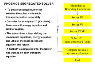
Understanding the impact of adjacent channel interference (ACI) and alternative ACI on system performance in 802.11ax simulations. Evaluation of ACI impairments on system performance and the calculation of out-of-band (OOB) emissions due to PA non-linearity using SM and EVM tables.
Please find below an Image/Link to download the presentation.
The content on the website is provided AS IS for your information and personal use only. It may not be sold, licensed, or shared on other websites without obtaining consent from the author. If you encounter any issues during the download, it is possible that the publisher has removed the file from their server.
You are allowed to download the files provided on this website for personal or commercial use, subject to the condition that they are used lawfully. All files are the property of their respective owners.
The content on the website is provided AS IS for your information and personal use only. It may not be sold, licensed, or shared on other websites without obtaining consent from the author.
E N D
Presentation Transcript
July 2014 doc.: IEEE 802.11-14/0865r1 ACI and AACI for 802.11ax System Simulations Date: 2014-07-16 Authors: Name Yu Cai Affiliations Address Huawei Technologies Phone +86-15692098770 email yu.caiyu@huawei.com Huawei Base, Bantian, Shenzhen, CHINA,518129 David X. Yang david.yangxun@huawei.com Submission Slide 1 Yu Cai, Huawei Technologies
July 2014 doc.: IEEE 802.11-14/0865r1 Summary Impact of Adjacent channel interference (ACI) or alternative adjacent channel interference (AACI) needs to be taken into consideration in system simulation Scenarios where overlap BSS working in adjacent channel or alternative adjacent channel have significant ACI and AACI problems, which are necessarily to be evaluated to determine its impact on system performance. Two types ACI impairments and their impact on system performance For blocker modeling in RX side, ACI is more in the form of band selection filter/blocker rejection filter residue and its negative impact also strongly associated with anti-aliasing filter. (ACI/AACI from RX perspective) AC/AAC leakage increases neighboring channel noise floor level, degrading CCA level detection sensitivity and receiver performance. The modeling is derived from SM and EVM specified in the standard at TX side and would be major theme of this slide. (ACI/AACI from TX perspective, plus the path loss, converted to essential impact/noise level in the RX) Submission Yu Cai, Huawei Technologies
July 2014 doc.: IEEE 802.11-14/0865r1 ACI/AACI due to OOB Emission 1. We focus on the calculation of OOB emission based on SM and EVM table shown in the following slide. 1. Calculation in TX side only needs to know the signal waveform in TX side. 2. Signal waveform might also be irregular. Fortunately, standard of 802.11 specify Spectrum Mask (SM) and relative constellation error (RCE=EVM). Arbitrary signal (MCSx) waveform can be derived from SM+EVM table based on the model proposed in this slide. 2. Calculation of ACI/AACI due to OOB Emission based on arbitrary signal waveform in TX side + effect of wireless channel can results in its impact on the receiver noise floor. Submission Slide 3 Yu Cai, Huawei Technologies
July 2014 doc.: IEEE 802.11-14/0865r1 OOB Emission and PA non-linearity 1. OOB Emission normally comes from non-linearity of PA, we also called it as out of band leakage. Normally we can used adjacent channel power ratio (ACPR) and alternative adjacent channel power ratio (AACPR) to evaluate it. But it also needs to calculate ACI and AACI. Then ACPR=Channel Power/ACI, AACPR=Channel Power/AACI. The other simple way of evaluating OOB Emission is through SM, which can give us qualitative impression how bad the ACI, AACI is. Normally SM represents the worst case of tolerable signal waveform. Rapp model can be used to evaluate how non-linearity of PA exert its impact on signal waveform. We can control the shape of signal waveform by changing backoff value from P1dB to adjust PA s non- linearity and its OOB Emission and ACI, AACI. The effect is shown in the next slides. 2. 3. 4. Submission Slide 4 Yu Cai, Huawei Technologies
July 2014 doc.: IEEE 802.11-14/0865r1 PA non-linearity vs. backoff value and its impact on ACP [2] (Rapp model p=3) PA Output 4x for 64-QAM with p=3 0 Backoff from Full Saturation -10 P = 3 -20 -30 backoff=3.4dB -40 dB -50 -60 backoff=4.6dB -70 backoff=8.1dB -80 backoff=12.0dB -90 -100 -2 -1.5 -1 -0.5 0 0.5 1 1.5 2 freq backoff=16.0dB Submission Slide 5 Yu Cai, Huawei Technologies
July 2014 doc.: IEEE 802.11-14/0865r1 Example: Simulation scenarios and path loss (PL) calculation TX2 PTX2=20dBm TX1 ch2 ch1 PTX1=17dBm Path loss can be calculated in terms of channel D path loss model. MCS3, d2=20m, 80MHz MCS0, d1=15m, 40MHz PRX1=PTX1-PL(15)=-49.27dBm PRX2=PTX2-PL(20)=-50.64dBm RX PL(d)=LFS (dBP)+35*log10(d/ dBP)+SF d> dBP =10m for Channel D SF=0, LFS (d)=20*log10(d)+20*log10(f)-147.5 f=2.4*10^9 Hz PL(d)= 20*log10(f)-147.5 +35*log10(d)-15*log10( dBP) f=2.4*10^9 Hz, dBP=10m PL(d1)=66.27dB PL(d2)=70.64dB Submission Slide 6 Yu Cai, Huawei Technologies
July 2014 doc.: IEEE 802.11-14/0865r1 Example: ACI and AACI calculation with 2 adjacent channel bandwidth of 40MHz ch2 ch1 ACPR|[chx,chy](dB)= Pchx(dB)-ACI|[chx,chy](dB) AACPR|[chx,chy] (dB)=P|chx(dB)-AACI|[chx,chy](dB) ACI calculation is by integrating all the signal power which leak to the adjacent band. ACPR|[chx,chy] is the adjacent channel power ratio between the signal in channel x and the leakage from the signal in channel x to channel y. Signal waveform in RX in CH1 Signal waveform in RX in CH2 Noise floor -60MHz -20MHz -100MHz 20MHz 60MHz P AACI File:WPint.svg ACI File:WPint.svg 20MHz -20MHz Pref|ch2 = Pref|ch1 = PSDch2 PSDch1 -20MHz -20MHz -60MHz 20MHz File:WPint.svg File:WPint.svg ACI|[ch2,ch1] = ACI|[ch1,ch2] = PSDch2 PSDch1 -60MHz -60MHz -20MHz 60MHz File:WPint.svg File:WPint.svg AACI|[ch2,ch1] = AACI|[ch1,ch2] = PSDch2 PSDch1 -100MHz 20MHz Submission Slide 7 Yu Cai, Huawei Technologies
July 2014 doc.: IEEE 802.11-14/0865r1 AC/AAC leakage in TX + Path Loss = Additive noise impact in RX Since it is assumed that signal waveform won t change due to different channels, the only difference of ACI/AACI between TX and RX is PL (Path Loss) ACI|[ch1,ch2]=PRX-ACPR =PTX-PL(d)-ACPR =PTX-ACPR-PL(d) AACI|[ch1,ch2]=PRX-AACPR =PTX-PL(d)-AACPR =PTX-AACPR-PL(d) where, ACI|[ch1,ch2] means ACI from ch1 to ch2 Submission Slide 8 Yu Cai, Huawei Technologies
July 2014 doc.: IEEE 802.11-14/0865r1 Calculation complexity due to two adjacent channels with different bandwidth and MCS 1. Bandwidth of major signal band (BW0) might not be equivalent to the bandwidth of the adjacent band (BWadj) or alternative adjacent band (BWaadj). For example, BW0 =40MHz, BWadj =20MHz, BWaadj =80MHz MCS of major signal band might not be equivalent to the MCS of the adjacent band (BWadj) or alternative adjacent band (BWaadj). For example, Major band=MCS3, Adjacent band=MCS5, Alternative adjacent band=MCS0. 3. In order to cover all these scenarios, signal waveform (SM function) scalability and quantization needs to be introduced. 2. Submission Slide 9 Yu Cai, Huawei Technologies
July 2014 doc.: IEEE 802.11-14/0865r1 SM Scalability (40MHZ to 80MHz) PSD PSD 0dBr 0dBr f(x/2) -20dBr -20dBr -28dBr -28dBr -40dBr -40dBr 120 80 -80 -120 19 21 -21 -19 60 -40 -60 40 39 41 38 42 -38 -39 -41 -42 Scaling of 40MHz piecewise SM is not equivalent to 80M SM. 80MHz SM 40MHz SM f40MHz(x/2) Submission Slide 10 David Xun Yang, Huawei Technologies
July 2014 doc.: IEEE 802.11-14/0865r1 Stepwise SM Scaling (40MHZ to 80MHz) PSD PSD 0dBr 0dBr fstep(x/2) -20dBr -20dBr -28dBr -28dBr -40dBr -40dBr 120 80 -80 -120 -21 -19 60 -40 -60 40 19 21 39 41 38 42 -38 -39 -41 -42 -20 20 -40 -40 Scaling of 40MHz piecewise SM is not equivalent to 80M SM. Submission Slide 11 David Xun Yang, Huawei Technologies
July 2014 doc.: IEEE 802.11-14/0865r1 SM Quantization----Due to piecewise line and scalability CH1 0dBr SM function normally is piecewise line function and on which integration for system simulator is not straightforward. We simplified it as step line function which makes life easier. -10dBr=[0+(-20)]/2 -24dBr =[(-20)+(-28)]/2 -20dBr -34dBr=[(-28)+(-40)]/2 -28dBr -40dBr -40dBr Noise floor -10MHz 10MHz -30MHz 30MHz 100MHz 20MHz SM function, quantized from green piecewise line SM function f(x) to step line function, fstep(x) aref,MCS0=0dBr 0<|x|<=10MHz a0,MCS0=-24dBr Arbitrary bandwidth SM function: fstep(x/N0) For example, SM|160MHz=fstep(x/8); 10MHz<|x|<=20MHz fstep(x)= a1,MCS0=-34dBr 20MHz<|x|<=30MHz a2,MCS0=-40dBr 30MHz<|x| Submission Slide 12 Yu Cai, Huawei Technologies
July 2014 doc.: IEEE 802.11-14/0865r1 Stepwise SM Scalability ( from 20MHz to 160MHz) fstep(x/2) where, fstep(x) is the function of SM @ 20MHz fstep(x/4) fstep(x/8) Submission Slide 13 Yu Cai, Huawei Technologies
July 2014 doc.: IEEE 802.11-14/0865r1 OOB Emission for 2 adjacent channel with arbitrary bandwidth -------based on stepwise line integration CH1 0dBr Note: Main channel bandwidth is BW0, adjacent channel bandwidth is BWadj, Alternative channel bandwidth is BWaadj. Here SM function f(x) at 20MHz used to represent MCS0 case. If major channel bandwidth is more than 20MHz, f(x/N0) is scaled to fit the scenarios, where N0 is the times of 20MHz. Nadj and Naadj represent times of adjacent, alternative adjacent channel channel to 20MHz. -20dBr -28dBr -40dBr Pref|BW0 ACI|[BW0,BWadj] AACI|[BW0,BWadj] Noise floor BW0/2+BWadj -BW0/2 BW0/2 BW0/2+BWadj+BWaadj Equation (1) can be simplified as File:WPint.svg BW0/2+BWadj File:WPint.svg 10MHz*N0 ACI|[BW0,BWadj] = fstep(x/N0)dx fstep(x/N0)dx Pref|BW0= (1) BW0/2 -10MHz*N0 File:WPint.svg a) BW0=20M*N0, N0=1,2,4,8 b) BWadj=20M*Nadj, Nadj=1,2,4,8 c) BWaadj=20M*Naadj, Naadj=1,2,4,8 10MHz*N0+10MHz*2Nadj fstep(x/N0)dx ACI|[BW0,BWadj] = 10MHz*N0 where, [BW0,BWadj] means interference from BW0 to BWadj, vice versa. ACPR|[BW0,Bwadj] = Pref|BW0 -ACI|[BW0,Bwadj] Submission Slide 14 Yu Cai, Huawei Technologies
July 2014 doc.: IEEE 802.11-14/0865r1 Quantized SM function for arbitrary MCSx CH1 RCE TABLE -10dBr MCS0 MCS3 -24dBr -34dBr -35dBr MCS0 -40dBr -45dBr (dB) =RCEMCS0(dB)-RCEMCS3(dB)=11dB MCS3 -51dBr Noise floor -10MHz 10MHz -30MHz 30MHz 100MHz SM of MCS3 is generated by pushing RCEMCS0- RCEMCS3=11dB down from MCS0 SM. 20MHz SM function, aref,MCSx=0dBr, 0<|x|<=10MHz where, =RCEMCS0-RCEMCSx a0,MCSx=-24dBr- , 10MHz<|x|<=20MHz fstep(x)|MCSx= Arbitrary bandwidth SM function: fstep|MCSx(x/N0) a1,MCSx=-34dBr- , 20MHz<|x|<=30MHz For example, SM|160MHz=fstep|MCSx (x/8); a2,MCSx=-40dBr- , 30MHz<|x| Submission Slide 15 Yu Cai, Huawei Technologies
July 2014 Generic equation for ACPR|[BW0,BWadj],MCSx andAACPR|[BW0,Bwadj],MCSx ch1 aref doc.: IEEE 802.11-14/0865r1 u(t) is Heaviside step function, -10dBr t<0 0, u(t)= 1, t>=0 -24dBr tadj=2*Nadj/N0; taadj=2*(Nadj+Naadj)/N0; BW1=10MHz*N0; Pref|BW0= aref*BW0=2*aref*BW1; -34dBr a0 MCS0 -40dBr (dB) =RCEMCS0(dB)-RCEMCSx(dB) a2 a1 MCSx BWadj BWaadj BW0 Noise floor -10MHz*N0 10MHz*N0 -30MHz*N0 30MHz*N0 1 ACI|[BW0,BWadj],MCSx= BW1*{ ai,MCSx*[(tadj-i)*u(tadj-i)-(tadj-i-1)*u(tadj-i-1)]+a2,MCSx*u(tadj-2) } i=0 ACPR|[BW0,BWadj],MCSx =Pref|BW0- ACI|[BW0,BWadj],MCSx =BW1*{2*aref,MCSx - ai,MCSx*[(tadj-i)*u(tadj-i)-(tadj-i-1)*u(tadj-i-1)]-a2,MCSx*u(tadj-2)} i=0 1 The above generic equation can be used to generate a look-up table in the next page. Submission Slide 16 Yu Cai, Huawei Technologies
July 2014 doc.: IEEE 802.11-14/0865r1 ACI and AACI calculation with known ACPR With the table of ACPR in slide 17, ACI is easy to calculate by a simple straightforward equation. So does AACI. Here if there is 3 channels ch1,ch2,ch3, ch2 is ch1 s adjacent channel and ch3 is ch1 s alternative adjacent channel. The MCSchx represent the MCS type of the chx. Then the generic equation of calculating ACI and AACI in TX side is as follows: ACI|[ch1,ch2] =PTX-ACPR |[BW1,BW2],MCSch1-PL(d) AACI|[ch1,ch3] =PTX-AACPR |[BW1,BW3],MCSch1-PL(d) where BWx represents the bandwidth of chx. More generally, the ACPR and AACPR can be calculated by the equation as shown in the page 16. Submission Slide 18 Yu Cai, Huawei Technologies
July 2014 doc.: IEEE 802.11-14/0865r1 Conclusion A generic method of ACI/AACI calculated based on TX side specification is proposed here from which generic analytic equations are developed and is easier to be migrated into system simulations. Two examples show how to use them in specific scenarios. Wireless channels is only models as large scale path loss which makes calculation of ACI in TX side plus path loss can be applied in the RX side to simulate the TX side OOB impairment on noise floor in RX side. Complicated integration method over signal waveform is replaced by summation of step line function over SM designed for different MCS. A generic function is given for calculating OOB emission or ACI/AACI in TX side under all scenarios which makes system simulator easier to take this effect into account without consuming too much calculation resources. Submission Yu Cai, Huawei Technologies
July 2014 doc.: IEEE 802.11-14/0865r1 Conclusion (Cont ) ACI/AACI due to AC/AAC leakage would have impact on noise floor level of the RX and CCA detection sensitivity CCA is a criteria to judge a channel if busy or not, it has strong correlation with ACI and AACI. The ACI and AACI would also have great impact on SNR when both channel are working simultaneously. Both channel SNR degradation can be calculated quantitatively by them. AACI calculation is mediocre generalization of ACI calculation while scenarios is much more complicated In system level simulations, ACI impact can be calculated by the table in slide 17. The ACI happens in scenarios for any adjacent channels which are not orthogonal, for example, OBSS in typical. The bandwidth would not be necessarily the same as the main channel. However, for alternative channel interference, since the scenarios might have much complicated cases (for example, main channel 20MHz, AC 40MHz, AAC 160MHz, etc.), the lookup table similar to ACPR table in slide 17 would be no doubt much larger. Submission Yu Cai, Huawei Technologies
July 2014 doc.: IEEE 802.11-14/0865r1 Open question for calculating ACI/AACI based on RX side specification 1. ACI, AACI calculation strongly depends on receiver architecture, for example, heterodyne receiver or direct conversion receiver. 2. The jamming effect evaluation due to ACI and AACI in RX side strongly associates with BB algorithm. Therefore, a generic method applied to different bandwidth and different MCS is difficult to derived. 3. ACI and AACI is specified in the standard as ACR and AACR which can be thought as a AC/AAC blocker when the main channel are 3dB above its sensitivity level. However, it doesn t specify how it will be migrated to generalized scenarios when the received signal is much higher above sensitivity and when main channel and AC bandwidth are different from each other. 4. Reasonable modeling ACI/AACI in RX side needs to take channel select/blocker rejection filter and anti-aliasing filter model into consideration, which has significant impact on receiver BB processing, PER, moreover, sensitivity. Submission Slide 21 Yu Cai, Huawei Technologies
July 2014 doc.: IEEE 802.11-14/0865r1 Reference Author Title Source Date 80-MHz Non-Contiguous Channel Spectrum 11-11-0063-00-00ac-80-mhz-non-contiguous- channel-spectrum [1] Tian-Wei Huang 2011-1 11-00-0393-00-000g-power-and-effects-for-hrb- ofdm [2] Paul Chiuchiolo, Mark Webster Power Amp Effects for HRb OFDM 2000-11 IEEE P802.15 Working Group for Wireless Personal Area Networks (WPANs) 15-04-0663-00-004b-recommendations-power- amp-model-and-multipath-rms-delay-spread [3] Colin Lanzl 2004-11 Spectral Mask Considerations for 802.11 HRb 11-00-0283-00-00sb-spectrum-mask- considerations-for-802-11-hrb [4] Mark Webster and Karen Halford 2000-09 Suggested PA Model for 802.11 HRb [5] Mark Webster 11-00-0294-00-00sb-suggested.. 2000-09 11-11-0160-00-000m-11n-spectrum-mask- alignment [6] Bijoy Bhukania 11n Spectrum Mask Alignment Submission Slide 22 Yu Cai, Huawei Technologies