Improved Damping Estimator Insights
Explore the OSEM Estimator for Improved Damping, discussing limitations at higher frequencies, the comparison between suspensions and seismic table measurements, and design concepts utilizing Z-Drive to actuators for better performance. These detailed insights shed light on enhancing damping abilities and sensor performance for improved results.

Download Presentation

Please find below an Image/Link to download the presentation.
The content on the website is provided AS IS for your information and personal use only. It may not be sold, licensed, or shared on other websites without obtaining consent from the author. If you encounter any issues during the download, it is possible that the publisher has removed the file from their server.
You are allowed to download the files provided on this website for personal or commercial use, subject to the condition that they are used lawfully. All files are the property of their respective owners.
The content on the website is provided AS IS for your information and personal use only. It may not be sold, licensed, or shared on other websites without obtaining consent from the author.
E N D
Presentation Transcript
OSEM Estimator for Improved Damping Brian Lantz Edgard Bonilla Pierce Garver DCC Number: G2401720 1
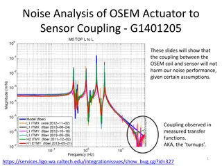
OSEM Limitations Reduced damping at higher frequency OSEM noise limits damping performance at higher frequencies OSEMs limit damping ability Inertial sensors on the ISI have better performance at higher frequencies Incorporating these inertial sensors can provide better measurements above 20 Hz enabling quieter damping A. Effler LLO LOG 68331 2
Suspensions vs Seismic Table Suspension: Suspension Point Seismic Table Measured by OSEM Gap STG 2 Gap, measured by CPS STG 1 Seismic Sensor 3
Design Concept Z Drive To Actuators Displacement Damper STG 2 OSEM 4
Design Concept Z Drive To Actuators Displacement Damper STG 2 Z Drive Drive to Gap Model Unit Time Delay Modeled Gap + Blend Filter Estim ator STG 1 to Gap Model Switch STG 1 Z + Measured Gap STG 2 OSEM Blend Filter 5
Design Concept Z Drive To Actuators Displacement Damper STG 2 Z Drive Drive to Gap Model Unit Time Delay Modeled Gap + Blend Filter Estim ator STG 1 to Gap Model Switch STG 1 Z + Measured Gap STG 2 OSEM Blend Filter 6
Design Concept Z Drive To Actuators Displacement Damper STG 2 Z Drive Drive to Gap Model Unit Time Delay Modeled Gap + Blend Filter Estim ator STG 1 to Gap Model Switch STG 1 Z + Measured Gap STG 2 OSEM Blend Filter 7
Design Concept Z Drive To Actuators Displacement Damper STG 2 Z Drive Drive to Gap Model Unit Time Delay Modeled Gap + Blend Filter Estim ator STG 1 to Gap Model Switch STG 1 Z + Measured Gap STG 2 OSEM Blend Filter 8
Design Concept Z Drive To Actuators Displacement Damper STG 2 Z Drive Drive to Gap Model Unit Time Delay Modeled Gap + Blend Filter Estim ator STG 1 to Gap Model Switch STG 1 Z + Measured Gap STG 2 OSEM Blend Filter 9
Design Concept Z Drive To Actuators Displacement Damper STG 2 Z Drive Drive to Gap Model Unit Time Delay Modeled Gap + Blend Filter Estim ator STG 1 to Gap Model Switch STG 1 Z + Measured Gap STG 2 OSEM Blend Filter 10
Design Concept Inertial Damper GS-13 Switch Z Drive To Actuators Displacement Damper STG 2 Z Drive Drive to Gap Model Unit Time Delay Modeled Gap + Blend Filter Estim ator STG 1 to Gap Model Switch STG 1 Z + Measured Gap STG 2 OSEM Blend Filter 11
Model Design Process 1 1 Model of gap motion ??? =??? ?0 ?0 ??? ???? ??? ?0 ?0 ?0 ???? ?0+ ???? ?0 ?0 Gap motion is the sum of STG 1 and STG 2 motion from a drive in STG 2 only Gap motion due to STG 1 Gap motion due to STG 1 motion ?0= STG 1 drive ?0= STG 1 response ????= Gap drive ???= Gap response STG 2 motion comes from drive and STG1 motion, but we are only interested in STG 2 motion from a drive in STG 2 Gap motion due to STG 2 motion from a drive in STG 2 Best results come from collecting discrete transfer functions, doing calculations with the data, then fitting the result as opposed to fitting the original discrete transfer functions and doing math on the continuous models STG 1 Motion STG 2 Drive Gap Motion STG 2 Motion 12
Gap Drive to Gap Model Fitting done using Gabriele Vajente s tool, interactive fitting powered by VEC FIT Accurate fit in region of interest Area not fit 13
Stage 1 Motion to Gap Model Fitting done using Gabriele Vajente s tool, interactive fitting powered by VEC FIT Accurate fit in region of interest Area not fit Area not fit 14
Stage 2 Damping Using CPS Damping controller for Stage 2 Z DOF using CPS sensors Specially designed to more accurately reflect observatory systems which use displacement sensors for damping Resonance at 3 Hz Simple lead filter to reduce the Q of the peak to less than 3 15
Estimator CPS Blend Blend filter used to combine estimator and measured gap Low pass takes gap measurement from CPS sensors at low frequency and in 3 Hz area Bump for resonance High pass takes the estimated gap at high frequency except for at the 3 Hz area 16
Model Performance Model Predictions Accurately tracks what the CPS measures Residual peaks at approximately 3 Hz. Most likely due to small mismatch in model resonant frequency and table resonant frequency Resonance Peak at 3 Hz ~1.5 order of magnitude improvement Residual limit is the difference between CPS noise and Estimator noise 17
Estimator Performance Black curve is using CPS measurements for damping. Measurement done by GS-13 Resonance damping at 3 Hz Pink curve is using estimator for damping. Measurement done by GS-13 ~1 order of magnitude improvement Order of magnitude improvement from 50Hz to 200Hz 18
Future Work / Improvements Test estimator on suspensions at observatories Safety for estimator stability in event of hardware shutoff Light plant damping to improve models Implementing a fader to move smoothly from one control to another Accounting for cross-coupling present in the suspension but not in the table used for this project 19
Questions Estimator Measurement 20