Improving Efficiency in Wireless Networks Through Spatial Reuse and Transmit Power Control
The document discusses the challenges and benefits of utilizing spatial reuse and transmit power control mechanisms in wireless local area networks. It highlights the importance of these techniques in enhancing network performance and efficiency. Spatial reuse aims to improve the utilization of available resources, while transmit power control helps in managing power levels effectively. The document also touches upon the difficulties in implementing power control in networks without centralized coordination. Overall, it emphasizes the significance of these mechanisms for optimizing wireless network operations.

Download Presentation

Please find below an Image/Link to download the presentation.
The content on the website is provided AS IS for your information and personal use only. It may not be sold, licensed, or shared on other websites without obtaining consent from the author. If you encounter any issues during the download, it is possible that the publisher has removed the file from their server.
You are allowed to download the files provided on this website for personal or commercial use, subject to the condition that they are used lawfully. All files are the property of their respective owners.
The content on the website is provided AS IS for your information and personal use only. It may not be sold, licensed, or shared on other websites without obtaining consent from the author.
E N D
Presentation Transcript
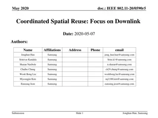
Sept 2018 doc.: IEEE 802.11-18/1531r3 TG ax Spatial Reuse DSC and TPC Date: 2018-09 Authors: Name Graham Smith Company Address SR Technologies Phone email gsmith@srtrl.com R2 edits R3 wrong reference Submission Slide 1 Graham Smith, SR Technologies
Sept 2018 doc.: IEEE 802.11-18/1531r3 I came across a Technical Paper on Spatial Reuse that is worthwhile sharing. Improving spatial reuse in future dense high efficiency Wireless Local Area Networks CITE: Imad Jamil. Improving spatial reuse in future dense high efficiency Wireless Local Area Networks. Networking and Internet Architecture [cs.NI]. INSA de Rennes, 2015. English. <NNT : 2015ISAR0033>. <tel-01329810> I will present excerpts from this together with observations. Submission Slide 2 Graham Smith, SR Technologies
Sept 2018 doc.: IEEE 802.11-18/1531r3 Cellular Scenario International Telecommunication Union (ITU) UrbanMicro (UMi) model defined by the ITU-R SG [87]? for hexagonal cell layout as follows: PL(dTR) = 22.7+36.7log(dTR)+26log( fc ) A modified version of this model is used within the cellular simulation scenario PL(dTR) = 23.3+36.7log(dTR)+21log(fc / 0.9) Submission Slide 3 Graham Smith, SR Technologies
Sept 2018 doc.: IEEE 802.11-18/1531r3 Challenges of Transmit Power Control (TPC) in WLAN systems Clause 4.4.2 It is interesting to note that TPC is standardized since 2003 by the IEEE 802.11h amendment but it has hardly found its way to the production stage. Although, for networks with centralized controllers, TPC is relatively simple to implement, it was only applied on APs but never on Station (STA)s. In such situations, the APs that are connected to a common controller apply TPC to reduce their transmit power, however the STAs associated to these APs still transmit with their full power. The main reason behind this is related to the nature of TPC which is selfless. If a node reduces its transmission power by applying the TPC, that will promote the neighboring transmissions because they are no more bothered by the transmissions of that node. Consequently, the other nodes will benefit directly and not the node that applied the TPC. Submission Slide 4 Graham Smith, SR Technologies
Sept 2018 doc.: IEEE 802.11-18/1531r3 Challenges of Transmit Power Control (TPC) in WLAN systems Moreover, in networks which lack a central regulator, power control proves to be much more difficult to implement and apply. Since centralized coordination between nodes is very difficult, it is necessary for each node to regulate its own transmission power autonomously. This behavior creates an asymmetric application of TPC and hence different transmission powers for different nodes. Again, the selfless feature of TPC will prevent real networks from taking this approach. The detrimental effect of this asymmetry is argued by many researchers. It has been proven that in such situation, TPC leads to the starvation of the unprivileged nodes. Actually, TPC is more problematic to achieve in a distributed manner becauseit will foster higher power transmitters, that are not applying power control, at the expense of lower power transmitters that are applying it. Submission Slide 5 Graham Smith, SR Technologies
Sept 2018 doc.: IEEE 802.11-18/1531r3 Dynamic physical carrier sensing adaptation Physical Carrier Sensing Adaptation (PCSA) In order to confirm the efficiency of PCS in enhancing spatial reuse in dense deployments and hence increasing the aggregate throughput of the network, a dynamic adaptation algorithm is proposed here and evaluated. .each device adapts its PCS threshold in terms of the power received from its communication peer. For instance, in an infrastructure BSS, all the communications are held between an AP and a STA. In such a case, the STA adapts its PCS threshold according to the power level received from its AP and vice-versa. Therefore the PCS threshold of each device is obtained as follows PCSth[dBm] = Rxp[dBm] M[dB] NOTE: This is the DSC formula where PCSth is OBSS_PD Submission Slide 6 Graham Smith, SR Technologies
Sept 2018 doc.: IEEE 802.11-18/1531r3 STA and AP setting of Rxp STA uses a moving average of received Beacon frames AP uses the minimum reception power from its associated STAs. NOTE : Again as proposed for DSC Example: Rxp = -55dBm, M = 20dB PCSth = -75dBm Submission Slide 7 Graham Smith, SR Technologies
Sept 2018 doc.: IEEE 802.11-18/1531r3 Cellular Scenario All PCSA STAs M=20dB all the transmitters are configured to transmit using the MCS7 (64-QAM modulation scheme and 5/6 coding rate). the application of PCSA leads to a gain of 126 % in aggregate throughput (from 45 Mbps to 102 Mbps). Submission Slide 8 Graham Smith, SR Technologies
Sept 2018 doc.: IEEE 802.11-18/1531r3 PCSA - With Rate Control Restricting the MCSs Best is restricting to MCS 5-7 and 4-7. In all cases PCSA has gain 260% to 500% Submission Slide 9 Graham Smith, SR Technologies
Sept 2018 doc.: IEEE 802.11-18/1531r3 PCSA With Rate Control The aggregate throughput only tells half the story. It is interesting to look at the worst case throughput performance represented by the central AP This AP, belonging to the central BSS, experiences the greater amount of interference from the surrounding BSSs Best is MCS 4-7 about 375% gain Submission Slide 10 Graham Smith, SR Technologies
Sept 2018 doc.: IEEE 802.11-18/1531r3 TPC Algorithm a new TPC algorithm that is fairly comparable to the PCSA described above. Each node adapts its transmit power so that its transmission is received at a margin above the traditional PCSth ( 82 dBm) by the intended receiver. In that way, the shrinking ratio of the sensitivity range is maintained the same as the PCSA case. This adaptation algorithm is used to compare the performance of TPC versus PCSA. Example: Rxp = -45dBm, hence received signal is (82-45)= 37 dB above threshold If M= 30dB, then TXPWR can be reduced by 37-30=7dB Thus TXPWRtpc = 15 7 = 8dBm Formula is: TXPWRtpc = TXPWR (Rxp-PCSth) +M Where PCSth = -82dBm Note this can be expressed as TXPWRtpc = TXPWR (OBSS_PD PCSth) where PCSth = -82 dBm and OBSS_PD = Rxp - M NOTE: This is what was proposed in linking DSC and TPC Submission Slide 11 Graham Smith, SR Technologies
Sept 2018 doc.: IEEE 802.11-18/1531r3 Cellular Scenario All TPC STAs Gain of 93 % in aggregate throughput Higher M means less TXPWR reduction. M=30dB M=25dB all the transmitters are configured to transmit using the MCS7 (64-QAM modulation scheme and 5/6 coding rate). TPC, M=30 Outer STA TXPWR = 15-(-55+82)+30= +18 dBm (i.e. no TPC) Inner STA TXPWR = 25-(-35+82)+30= -2 dBm AP TXPWR = +18 dBm ? (So no TPC?) Submission Slide 12 Graham Smith, SR Technologies
Sept 2018 doc.: IEEE 802.11-18/1531r3 Presence of Legacy devices 1 legacy STA per cell in the case of TPC, we can see that the presence of 7 legacy STAs causes more than 35 % of aggregate throughput decrease For the PCSA approach, the maximum aggregate throughput is decreased by 10 % compared to the case where there are no legacy devices It is clear that PCSA shows greater ability to tolerate the presence of legacy devices than TPC. Submission Slide 13 Graham Smith, SR Technologies
Sept 2018 doc.: IEEE 802.11-18/1531r3 Balanced Transmit power control and Physical carrier sensing Adaptation in the presence of a given number of legacy devices, the aggregate throughput decreases by 10 % when applying PCSA while it decreases by 35 % when applying TPC (see Section 4.8.4 for details). It is true that in the presence of legacy devices, the PCSA overall performance does not suffer from serious degradation as that of TPC. However, the fairness between the contending nodes is altered. Propose a scheme, BTPA, that combines both PCSA and TPC PCSth = Rxp[dBm] M[dB] x [dB] = PCSth PCSdefault [dBm] (-82dBm) tpc = ratio x x pcs = x - tpc TXPWR = TXPWR - tpc PCSth = PSCth + pcs Example: Rxp = -45dBm, M=20, ratio 0.5 PCSth = -45 20 = -65dBm x = -65 + 82 = 17 dB tpc = 17 x 0.5 = 8.5dB, pcs = 17 7.5 = 9.5dB, TXPWR = 15 8.5 = 6.5 dBm PCSth = -65 8.5 = -73.5 dBm Submission Slide 14 Graham Smith, SR Technologies
Sept 2018 doc.: IEEE 802.11-18/1531r3 For all of the three configurations, when the BTPA s ratio is below 0.4 the average throughput achieved by the 802.11ax STAs is quite stable at its maximum attained level. The legacy STAs are almost not able to transmit for these values of BTPA s ratio. This observation is reasonable recalling the fact that PCSA favors the 802.11ax nodes kills legacy traffic. Increasing the ratio above 0.5 increases the average throughput achieved by the legacy STAs. For a ratio around 0.7, the averaged throughputs achieved by all the nodes are very close. TPC kills the 802.11ax traffic Submission Slide 15 Graham Smith, SR Technologies
Sept 2018 doc.: IEEE 802.11-18/1531r3 Points on this work Not my work and I had several questions, BUT, the following points may be taken away from this work: 1. If using OBSS_PD procedure, better if STAs select value based upon the Beacon RSSI 2. Legacy STAs present problems and a combined TPC PCSA (DSC) approach has merit. Submission Slide 16 Graham Smith, SR Technologies
Sept 2018 doc.: IEEE 802.11-18/1531r3 Conclusions Setting the OBSS_PD based upon the Beacon RSSI should be added to the 11ax Draft As proposed in 18/0617 OBSS_PDlevel = RSSI_beacon OBSS_PD_Margin With OBSS PDmin <OBSS_PDlevel < OBSS_Pdmax This allows a mix of PCSA and TPC PCSA Physical Carrier Sense Adaptation Submission Slide 17 Graham Smith, SR Technologies
Sept 2018 doc.: IEEE 802.11-18/1531r3 Straw Poll Resolve CID 15652 to allow an AP to include the OBSS_PD Margin and to allow a STA to adjust its ODSS_PD level in accordance with OBSS_PDlevel = RSSI_beacon OBSS_PD_Margin With OBSS PDmin <OBSS_PDlevel < OBSS_Pdmax Note to Assignee: CID proposed accepting text in 18/0617r2 which referenced D2.2 18/0617r3 is now posted referring D3.0 Submission Slide 18 Graham Smith, SR Technologies
Sept 2018 doc.: IEEE 802.11-18/1531r3 Other information Submission Slide 19 Graham Smith, SR Technologies
Sept 2018 doc.: IEEE 802.11-18/1531r3 Background Previous presentations have analyzed DSC and the various scenarios: By Graham Smith Dynamic Sensitivity Control 13/1012r4, 13/1290r1 Dense Apartments 13/1487r2, 14/0328r2 Airport capacity 13/1489r5 Pico Cell 14/0058r1 E_Education 14/0045r2 Enterprise Scenario 15/0548r0 DSC and Roaming 15/0025r0 DSC Practical Usage 14/0779r2 DSC Channel Select and Legacy sharing 14/0294r0 Outdoor Enterprise Scenario and DSC 15/0804r0 DSC Summary 15/0807 Adjustment of Sensitivity and/or CCA 16/0121 Enterprise Scenario DSC and Color 16/0212 Enterprise scenario TPC and DSC 16/0350 Indoor Enterprise Scenarios, Color, DSC and TPC 16/0597 Proposal for DSC, ATPC Inter_BSS with responses to Comments 16/1567 DSC as OBSS_PD 17/0163 OBSS_PD/TPC Examined 17/0582 By Others MAC Simulation Results for DSC and TPC 14/0523, Laurent Cariou (Orange) DSC and Legacy Coexistance 14/0854, William Carney (Sony) UL & DL DSC and TPC MAC Simulations 14/1171 Johan Soder (ericsson) DSC Simulation Results for Scenario 3 14/1171 Masahito Mori (Sony) Performance Analysis of B SS Color and DSC, 14/1403, Masahito Mori (Sony) DSC and legacy coexistence 14/1426 Gustav Wikstrom (Ericsson) DSC Performance 14/1427, Gustav Wikstrom (Ericsson) Simulation based Evaluation DSC in residential scenario, 15/0027, M Shahwaiz Afaqui (UPC) Impact of TPC coupled to DSC for legacy unfairness issue, 15/0319 Masahito Mori (Sony) Proposal and simulation based evaluation of DSC-AP Algorithm 15/0371, Eduard Garcia-Villegas (UPC) Discussion on the Receiver Behavior for CCAC DSC with BSS Color, 15/0595 Yasuhiko Inoue (NTT) Reference Simulation Model for Dynamic CCA / DSC calibration 15/0652, Masahito Mori (Sony) DCCA/DSC Reference Simulation Results. 15/0801, Masahito Mori (Sony) DSC/DCCA Calibration with Tgax Agreed Scenarios DSC calibration results with NS-3, 15/1316 Eduard Garcia-Villegas (UPC) Simulation Based evaluation of DSC in Enterprise scenario, 16/0604, Tanguy Ropitault, (NIST) Submission Slide 20 Graham Smith, SR Technologies
Sept 2018 doc.: IEEE 802.11-18/1531r3 Signal Levels STA randomly placed between 2 and 5m from AP AP to AP = -73 dBm (21m) AP to STA = -35 to -55 dBm (2m, 5m) overlap 3 3 TPC, M=30 Outer STA TXPWR = 15-(-55+82)+30= +18 dBm ? Inner STA TXPWR = 15-(-35+82)+30= -2 dBm AP TXPWR = +18 dBm ? (So no TPC?)* 6 3 3 Closest OBSS STA to STA = -63dBm (11m) Furthest OBSS STA to STA = -79 dBm (31m) So overlap even with TPC Expect center to be shut out Legacy DSC, M=20 Outer STA PCSth = -75dBm (OBSS_PD) Inner STA PCSth = -55dBm (OBSS_PD) 3 3 Notes: *For TPC if M< 27, then we have a circular condition if TPC is applied to AP outermost STA reduces power based on beacon power, which reduces AP power, which reduces beacon power etc. Not able to confirm if TPC was applied to AP suspect it can t be. Submission Slide 21 Graham Smith, SR Technologies