Information Sources, Signals, and Data Communication
Explore the intersection of physics, mathematics, and electrical engineering in data communication, analyzing information sources, analog vs. digital signals, sine waves, and composite signals like Fourier transform. Discover the essentials of effective communication and signal characteristics.

Download Presentation

Please find below an Image/Link to download the presentation.
The content on the website is provided AS IS for your information and personal use only. It may not be sold, licensed, or shared on other websites without obtaining consent from the author. If you encounter any issues during the download, it is possible that the publisher has removed the file from their server.
You are allowed to download the files provided on this website for personal or commercial use, subject to the condition that they are used lawfully. All files are the property of their respective owners.
The content on the website is provided AS IS for your information and personal use only. It may not be sold, licensed, or shared on other websites without obtaining consent from the author.
E N D
Presentation Transcript
6-Information Sources and Signals Dr. John P. Abraham Professor UTRGV
The Essence of Data Communication Intersection of Physics, Mathematics and Electrical Engineering Current, light, other electro-magnetic radiation, digitization, Fourier transform, etc. The source of information can vary, all using a single physical medium. Sender medium receiver Effective communication requires feedback
Information Sources Computer peripherals, microphones, sensors, measuring devices, etc. Analog or Digital Signals Analog is continuous change Digital is discrete change at fixed intervals Periodic and Aperiodic Signals Periodic repeats itself
Sine waves and signal characteristics Many natural phenomena occur in sine waves Electromagnetic radiation, sound, water waves, etc. There are 4 important characteristics of sine wave signals Frequency the number of oscillations per second Amplitude - the difference between maximum and minimum signal heights Phase - How far start of the sinwave is shifted from a reference time Wavelength length of a cycle (speed with which the signal propagates)
Sine Wave The sine wave or sinusoid is a mathematical function that describes a smooth repetitive oscillation. It occurs often in pure mathematics, as well as physics, signal processing, electrical engineering and many other fields. Its most basic form as a function of time (t) is: where: A, the amplitude, is the peak deviation of the function from its center position. , the angular frequency, specifies how many oscillations occur in a unit time interval, in radians per second , the phase, specifies where in its cycle the oscillation begins at t = 0. When the phase is non-zero, the entire waveform appears to be shifted in time by the amount / seconds. A negative value represents a delay, and a positive value represents a "head-start".
Composite signals Most signals are classified as composite because the signals can be decomposed into several simple waves. Signals generated by modulation are usually composite. A mathematician named Fourier discovered that it is possible to decompose a composite signal into its constituent parts. Fourier transform is used to solve many problems in science and engineering
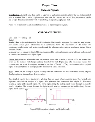
Analog and Digital signals Analog is characterized by continuous mathematical function. When input changes from one value to the next it does so by moving through all possible intermediate values. Digital has a fixed set of valid levels, and each change consists of an instantaneous move from one level to another.
Periodic and Aperiodic Signals A periodic signal repeats the pattern. Aperiodic does not repeat the pattern
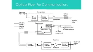
THEORETICAL BASIS FOR DATA COMMUNICATION TRANSMIT ON WIRES BY VARYING PHYSICAL PROPERTY VOLTAGE CURRENT FREQUENCY PHASE TRANSMIT ON GLASS FIBER BY SENDING LIGHT PULSES
Data Rate How much data can be sent in a given time? Depends on number of signal levels and time it remains in each signal level before going to the next. If we reduce the time at each signal level, more data can be sent. But there is minimum to time required to detect the signal. Engineers measure the inverse: how many times the signal can change per second which is measured as baud. If signal remains for .001 sec, it is 1000 baud. If the system has 2 signal levels, then 1000 bits can be transmitted with 1000 baud. If it has 4 signal levels, 2000 bits can be transmitted.
Bandwidth of analog and digital signals Difference between the highest and lowest frequencies of constituent parts as yielded by Fourier analysis. Digital signals: some systems use voltage to represent digital values. Only two levels of voltage indicate 0 or 1. Multiple levels of voltage may be used to indicate multiple bits. -5 volt = 00, -2 volt = 01, +2 volt = 10, +5 volts = 11 If multiple levels are used electronics must be sensitive enough to distinguish between voltage levels.
Bandwidth of a Digital signal Applying Fourier analysis we find a digital signal has infinite bandwidth because a digital signal produce an infinite set of sine waves.
Analog/Digital data Digital Data to Digital Signals Digital Data to Analog Signals Analog Data to Digital Signals Analog Data to Analog Signals
Converting digital to analog. Why do that? To transmit digital data over analog lines. Serial communication using modems. Basis of analog signaling is a continuous constant frequency known as the carrier signal.
Digital Data to Analog Signals ASK FSK PSK Go to notes here to talk about modem, null modem, dce (data communication equipment), dte (data terminal equipment). Students must know these concepts.
Digital Data to Digital Signals Digital signal is a sequence of discrete discontinuous voltage pulses. Each pulse is a signal element. Unipolar only positive voltage. Polar both positive and negative. NRZ Multilevel Binary Bipolar-AMI Pseudoternary Biphase Manchester and differential Manchester
Non return to zero (NRZ) and NRZi Easiest way to encode. Use 2 diff voltage levels. During a bit transmission the voltage does not return to zero NRZi non return to zero, invert on ones. No transition zero. Transition one In a twisted pair, if sending and receiving wires are improperly connected, nrzi is not affected. NRZ-I is an example of differential encoding. In decoding adjacent elements are compared for polarity changes. Draw it on the board.
Multilevel Binary This technique uses more than two signal levels. Bipolar AMI (alternate mark inversion) A binary 0 is represented by no line signal. Binary 1 is represented by a positive or negative voltage. The binary ones must alternate in polarity. Draw it. Advantage: no loss of synchronization in case of continuous one s transmitted. Receiver can synchronize with each transmission.
Biphase Manchester code There is a transition at the middle of each bit period This transition serves as a clocking mechanism. Low to hight represents 1 and high to low represents a 0.
Ethernet Encoding For 10 Mb/s Manchester Encoding. Idea is to detect a transition rather than voltage levels to define bits. For 100 Mb/s NRZ-I and MLT-3. For 1000 Mb/s - copper cable based Gigabit Ethernet (1000BASE-T), a pair of encoding methods was chosen, 8B1Q4 and 4D-PAM5. For fiber optic based Gigabit Ethernet (1000BASE-X), a different pair of encoding methods was chosen, 8B10B and NRZ.
MLT-3 MLT-3 is an encoding method used on Fast Ethernet 100BASE-TX networks. It is similar to Manchester encoding in that a logic '1' is represented by a voltage transition. However, whereas a Manchester encoded signal uses a two-state waveform (0V or +V), an MLT-3 encoded signal uses a three-state waveform (- V or 0V or +V.)
8B1Q4 and 4D-PAM5 Encoding 0n 1000BASE-T all four wire pairs must be used simultaneously in parallel when transmitting or receiving. To achieve the 1000Mbps data rate, each wire pair must be able to transmit or receive at a data rate of 250Mbps. the signal is first encoded using 8B1Q4 and then the 4D-PAM5 encoding method is applied after.
Analog Data to Digital Signals PCM pulse code modulation DM-delta modulation .
Encoding and Data compression Lossy some information is lost during compression JPEG MPEG Lossless all information is retained in the compressed version Repeated strings are compressed and a dictionary is created. Compressed data along with dictionary is sent to recreate the original data
Analog Data to Analog Signals AM FM PM


 and NRZi")