Innovations in LGAD and RSD Designs for High-Temporal Spatial Resolutions
Explore how the LGAD and Resistive Charge Division (RSD) designs have revolutionized silicon detectors, enhancing temporal and spatial resolutions. Discover the collaborative efforts behind these innovations and the implications for sensor and ASIC systems. Uncover the secrets to achieving good temporal resolution with LGADs and the impact of signal-to-noise ratios. Delve into the concepts of gain, noise, and the effective use of low gain for improved signal-to-noise ratios in LGADs.

Download Presentation

Please find below an Image/Link to download the presentation.
The content on the website is provided AS IS for your information and personal use only. It may not be sold, licensed, or shared on other websites without obtaining consent from the author. If you encounter any issues during the download, it is possible that the publisher has removed the file from their server.
You are allowed to download the files provided on this website for personal or commercial use, subject to the condition that they are used lawfully. All files are the property of their respective owners.
The content on the website is provided AS IS for your information and personal use only. It may not be sold, licensed, or shared on other websites without obtaining consent from the author.
E N D
Presentation Transcript
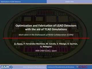
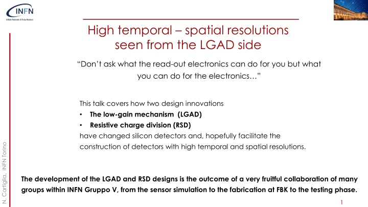
High temporal spatial resolutions seen from the LGAD side Don t ask what the read-out electronics can do for you but what you can do for the electronics This talk covers how two design innovations The low-gain mechanism (LGAD) Resistive charge division (RSD) have changed silicon detectors and, hopefully facilitate the construction of detectors with high temporal and spatial resolutions. N. Cartiglia, INFN Torino The development of the LGAD and RSD designs is the outcome of a very fruitful collaboration of many groups within INFN Gruppo V, from the sensor simulation to the fabrication at FBK to the testing phase. 1
One system: sensor and ASIC Sensors produce a current pulse The read-out measures the time of arrival One single system Sensors and read-out are two parts of a single object, sometimes even on the same substrate Sensors and electronics succeed (or eventually fail) together N. Cartiglia, INFN Torino In timing circuits, things can go wrong very rapidly (C. de La Taille) ==> This is not a simple evolution of what we know how to do. 2
Why do LGADs allow good temporal resolution? Sensors produce a current pulse The read-out measures the time of arrival One single system The secret is the signal-to-noise ratio N. Cartiglia, INFN Torino 3
Signal and noise in LGAD Caveat: noise is a boring subject, but you have to endure this slide to reach a brighter future. n++ electrode Gain layer First concept: gain (G) increases the signal (I): ?????? = ? ??????? Signal path p++ electrode Second concept: gain increases noise more than increases the signal ???????= ? ??????? ? ? = ?? + 2 1 N. Cartiglia, INFN Torino Excess noise factor: noise of the multiplication process (1 ?) ? Conclusion: internal gain decreases the signal-to-noise ratio of the signal (not good so far..) k = h/e ionization rate G = gain Use electron-initiated avalanche ==> lower noise than holes-initiated avalanche 4
Signal, noise in LGAD + Electronics Why do LGADs work then? Noise floor 1) The electronics has a noise floor 2) The signal increases with gain 3) The noise increases with gain with steeper characteristics Signal 4) The total noise is flat at low gain, Total Noise Amplitude and then it increases fast Best S/N ratio Low gain needs to be understood in connection with the noise of the electronics: it is the range of gain with an improved signal-to-noise ratio. The success of LGADs rests on the fact that the multiplication noise is hidden by the electronic noise Shot/multiplication Noise N. Cartiglia, INFN Torino Noise floor, gain independent 10 100 Low gain Signal (gain) 5
How gain shapes the signal To fully exploit LGADs, dedicated electronics needs to be designed. The signal from LGADs is different from that of traditional sensors 50 m thick sensor 50 m thick sensor Q = 0.5 fC Gain = 20 Q = 10 fC LGAD signals are actually slower than those of a standard silicon sensor, with a bandwidth of about 300-500 MHz (50-micron thick sensors) N. Cartiglia, INFN Torino Weightfield2 Pads with no gain Charges generated uniquely by the incident particle Pads with gain Current due to gain holes creates a longer and higher signal 2 sensors 6
Intrinsic LGAD time resolution Why LGAD have an intrinsic time resolution? Because the signal change shape on an event-to-event basis due to non-uniform energy deposition along the particle path WF2 Simulated energy deposits 15-micron thick sensor 80-micron thick sensor Large energy deposits are more likely in thicker sensors N. Cartiglia, INFN Torino The temporal resolution is degraded if one energy deposit is much larger than the average. Thick sensors have worse temporal resolution because it is more likely that at least one energy deposit is much larger (local Landau fluctuation in the energy deposition) 7
Non uniform ionization Shape distortion Amplitude variation WF2 simulation shows how the current signal changes. Two effects: 1. Amplitude variations 2. Shape distortions N. Cartiglia, INFN Torino WF2 simulation of signals generated by a MIP crossing a 50-micron thick UFSD, gain ~ 20 8
LGAD temporal resolution vs sensor thickness LGAD intrinsic temporal resolution improves in thinner sensors: ==> reasonable to expect 10-20 ps for 10-20 m thick sensors. 10 fC (gain = 20) 4 fC (gain = 20) Note: Thin sensors ==> small signals Difficult to do timing with small signals N. Cartiglia, INFN Torino 9
State-of-the-Art LGAD based systems Both the ATLAS and CMS experiments use for their timing layer large LGAD pixels (1.3 x1.3 mm2) ETROC2 TSMC, 65 nm CMOS process ToA and ToT Self calibrating TDC About 3 mW/channel CMS ETROC read-out ASIC: 35-40 ps, uniform over 256 pixels CMS ETL 16x16 array Distribution of the 256 ETROC2 pixels N. Cartiglia, INFN Torino 10
LGAD advantage for high temporal resolution Large signal (5-10 fC) Fast risetime (300-500 ps) Small intrinisc temporal resolution (10 30 ps, depending on thickness) Pixels of any size, from very large (1.3 x 1.3 mm2) to very small (55 x 55 micron2, TimePix compatible) Trench Isolated LGADs work well with small pitch N. Cartiglia, INFN Torino 11
Spatial resolution In standard applications with hybrid design, the position resolution determines: The pixel size The space available for the electronics. Good position resolutions implies the use of small pixels ASIC Sensor N. Cartiglia, INFN Torino 12
A low-power solution: resistive charge division n+ n++ ? ~ ?????/ ?? p++ p-bulk Silicon detector with resistive charge division Silicon detector with standard read-out In resistive charge division, instead of many p-n diodes, there is a single diode. The n-doped implant is resistive and acts as a signal divider Very uniform Electric and Weighing fields Charge sharing happens on the surface, not during e/h drift N. Cartiglia, INFN Torino Signal sharing is the key ingredient to excellent spatial resolution 13
Signal sharing in resistive silicon detectors The signal sees several impedances in parallel, and it is split according to Ohm s law. Each pad gets a share of the total signal, exactly as in a current divider 1 ?? ?1 ?? 1 2 ?? ?? ?? ?? ?? ?? 1 ?? ?? N. Cartiglia, INFN Torino ?? 3 4 14
Signal shape: square pixel, 500-micron pitch Let s look at the signal shape: A particle hits the detector The signal is shared among the 4 electrodes N. Cartiglia, INFN Torino 15
Signal shape: square pixel, 500-micron pitch The picture shows the amplitude recorded by 4 electrodes, The signal is fast, same shape of a standard LGAD. Accurate position reconstruction requires a good amplitude measurement. N. Cartiglia, INFN Torino 16
RSD resolution: depends on signal/noise N. Cartiglia, INFN Torino The key to good position resolution: precise amplitude reconstruction and low noise 17
State-of-the-art: 500-micron pitch DC-RSD 20 micron 40 ps Spatial resolution: less than 5% of the pitch Temporal resolution: Similar to standard LGAD N. Cartiglia, INFN Torino DC-coupled RSDs achieve excellent concurrent spatial and temporal resolutions with large pixels, reducing by about 100 the number of read-out channels 18
Final goal of RSD R&D: a completely new tracker Pixel size ~ 25 x 25 m2 Electronics Pixel size ~ 250 x 250 m2 ~ 150 m ~ 50 m Contacts -- --- - -- + ++ +++ Resistive implant --- - -- ++ +++ Silicon bulk Gain implant LGAD-RSD-based tracker Standard Tracker The design of a tracker based on RSD is truly innovative: It delivers ~ 20 -30 ps temporal resolution For the same spatial resolution, the number of pixel is reduced by 50-100 The electronic circuitry can be easily accomodated The power consumption is much lower, it might even be air cooled (~ 0.1-0.2 W/cm2) The sensors can be really thin N. Cartiglia, INFN Torino 19
The WF2 sensor simulator The design of pico-second front-end electronics needs to know what type of current signals the front end will receive. For this reason, we designed a simulator able to simulate the current pulse generated by silicon sensors accurately It includes: Custom Geometry Calculation of drift field and weighting field Currents signal via Ramo s Theorem Gain Diffusion Temperature effect Non-uniform deposition Electronics N. Cartiglia, INFN Torino WeightField2, Available at http://personalpages.to.infn.it/~cartigli/weightfield2 20
A library of signal shapes As a tool for ASIC designers, we have created a library of signal shapes to test a given design. This has been very important in the development of the FASTs and ETROC ASICs N. Cartiglia, INFN Torino 21
LGAD and RSD read-out N. Cartiglia, INFN Torino 22
Pre-amplifier choice: signal, noise and slope Signal dV/dt Landau Noise Excess noise factor Electronic Noise 50 micron sensor gain = 15 tCur tCur tAmp R tRC C N. Cartiglia, INFN Torino There are 3 quantities determining the output rise time after the amplifier: 1. The signal rise time (tCur ) 2. The RC circuit formed by the detector capacitance and the amplifier input impedance (tRC ) 3. The amplifier rise time (tAmp) 23
LGAD: What is the best pre-amp choice? Energy deposition in a 50 mm sensor Fast slew rate Higher noise Current Amplifier The best solution depends on the specifics of the detector: aimed resolution, channel density, power budget, etc Current signal in a 50 mm sensor Charge Sensitive Amplifier N. Cartiglia, INFN Torino Slower slew rate Quieter 24
DC RSD front-end amplifiers The amplifiers are connected to the same n+ sheet. For the read-out to work, the amplifiers should polarize the sensor to the same reference level. If this does not happen, the various amplifiers will start fighting each other to esthablish a given voltage value on the n+. n+ resistive sheet Input into an RC DC level uniform at 0.V N. Cartiglia, INFN Torino Input into a transistor, DC level non uniform, about 0.7 V This design works This design does not work 25
RSD: What is the best ASIC architecture? V Time over Threshold: TDC to measure Time of Arrival (ToA),t2 Time walk correction using ToT ToT = ToA t2 - ToA ToT needs to be proportional to the signal amplitude 1 2 Vth ToA t2 t 3 4 A Need to measure accurately: Time of arrival (for timing reconstruction) Signal amplitude (for position reconstruction) ToA and Amplitude: TDC to measure ToA ADC to measure Amplitude Time walk correction using Amplitude It is going to be a very interesting R&D V N. Cartiglia, INFN Torino Vth Presently, there are no ASICs designed specifically for RSD. ToA t 26
RSD: the final frontier Samples 1 2 Position Time ?? ?? Machine Learning Reconstruction code ?? ?? 3 4 (1) (2) (3) N. Cartiglia, INFN Torino Multiple sampling frontend Simpler design: Time-over-threshold Using the raw samples, an AI engine will provide position and time RSD sensor 27
Conclusions and outlook Two design innovations: The low-gain mechanism (LGAD) Resistive charge division (RSD) have radically changed how silicon sensors work. The LGAD mechanism is key to both high temporal and spatial resolutions as it increases the signal without increasing the noise LGAD can be designed even for very small pixels thanks to the introduction of trench- isolation N. Cartiglia, INFN Torino Resistive charge sharing offers the possibility of designing low-power detectors with excellent temporal and spatial resolutions. 28
Bibliography FAST3: FAST3: Front-End Electronics to Read Out Thin Ultra-Fast Silicon Detectors for ps Resolution, A. M. Rojas, et al., 2022 IEEE Latin American Electron Devices Conference (LAEDC), Cancun, Mexico, 2022, pp. 1-4, doi:10.1109/LAEDC54796.2022.9908192. FAST2: Amplifier discriminator ASICs to read-out thin Ultra-Fast Silicon detector for ps resolution, A. Rojas et al., 2021 IEEE Nuclear Science Symposium and Medical Imaging Conference (NSS/MIC), Piscataway, NJ, USA, 2021, pp. 1-4, doi: 10.1109/NSS/MIC44867.2021.9875441. FAST: Design and characterization of the FAST chip: a front-end for 4D tracking systems based on Ultra-Fast Silicon Detectors aiming at 30 ps time resolution, E. J. Olave et al., NIMA 985 (2021) 164615, HSTD12 A multichannel front-end readout ASIC for picosecond time resolution systems based on UFSD, E. J. Olave et al., JINST 15. C07012-C07012. 10.1088/1748-0221/15/07/C07012 July 2020 FAST: a 30 ps time resolution front-end ASIC for a 4D tracking system based on UFSD, F. Fausti, J. Olave, N. Cartiglia, TWEPP 2019 TOFFEE: Laboratory and beam test results of TOFFEE ASIC and Ultra Fast Silicon Detectors, R. Arcidiacono et al., PoS TWEEP 251, DOI: https://doi.org/10.22323/1.313.0028 N. Cartiglia, INFN Torino TOFFEE: a full custom amplifier-comparator chip for timing applications with silicon detectors, F. Cenna et al., JINST 12 (2017) C03031 Weigthfield2: Weightfield2:a fast simulator for silicon and diamond solid state detector, F. Cenna et al., NIMA 796 (2015) 149-153 29
Time resolution ? ????? ??/?? ?= + ???????????+ ?????? ?? Jitter term Signal shape is determined by Ramo s Theorem i qvEw Small noise ==> choice of electronic technology Large dV/dt ==> use sensors with internal gain Amplitude variation ==> corrected offline (time walk) Non-homogeneous energy deposition ==> signal change variation. Cannot be corrected, =minimized by design N. Cartiglia, INFN Torino Saturated drift velocity v everywhere in the sensor volume Uniform weighting field Ew Minimized by sensor design Minimized by sensor and electronics design Minimized by sensor design 30
State-of-the art Physicist No gain area ~ 50 um No gain area ~ 5 um JTE + p-stop design Trench-isolated design RSD -- AC-LGAD JTE/p-stop UFSD CMS && ATLAS choice Signal in a single pixel Not 100% fill factor Very well tested High Occupancy OK Rate ~ 50-100 MHz Rad hardness ~ 2-3E15 n/cm2 UFSD evolution: use trenches Signal in a single pixel Almost 100% fill factor Temporal resolution (50 m) : 35-40 ps High Occupancy OK Rate ~ 50-100 MHz Rad hardness: to be studied RSD evolution: resistive readout Signal in many pixels 100% fill factor Excellent position resolution: ~ 5 m with large pixels Temporal resolution (50 m) : 35-40 ps Rate ~ 10-50 MHz Rad hardness: to be studied N. Cartiglia, INFN Torino HPK2 16x16 31
The 1 m project Samples 1 2 Position Time ?? ?? Machine Learning Reconstruction code ?? ?? 3 4 (1) (2) (3) N. Cartiglia, INFN Torino Multiple sampling frontend Simplest design: Time-over-threshold Multi-inputs regression task Trained using laser and beam test data RSD sensor 32
Irradiation effects on LGAD Irradiation causes 3 main effects: Decrease of charge collection efficiency due to trapping Doping creation/removal Increased leakage current, shot noise The main effect in LGAD is acceptor removal , i.e., the reduction of the gain implant doping The electric field due to the gain implant decreases Compensated with higher bias Main technique to decrease acceptor removal: carbon implantation in the gain layer carbon implantation N. Cartiglia, INFN Torino 33
LGAD signal vs sensor thickness iMax Gain i(t) medium thick thin t3 t2 t1 t N. Cartiglia, INFN Torino As the sensor gets thinner: The amplitude stays constant The rise time becomes faster The rise time depends only on the sensor thickness ~ 1/d 34
Why RSDs are well suited for future experiments? Sensor property Experimental feature Innovation Continuous gain layer 100% fill factor Uniform weighting field Continuous cathode Uniform carriers drift velocity Resistive read-out Reduced power consumption Large pixels Space for electronics Excellent spatial precision Signal sharing N. Cartiglia, INFN Torino Thin Low material budget Internal gain 100% efficiency Large signals Excellent temporal precision 35
Temporal reconstruction method Step 1: For each electrode, estimate the time of the hit ?? Measure the time of arrival?? (constant fraction discriminator at 30%) t1meas ??? t1offset ???? 1 2 t1delay = v * di ?????= ? ?? Correct for signal delay ?? Correct for set-up offset ?? ?????? ?????? ????? + ?? ???=?? ???? + ?? ?? 3 4 Step 2: Combine the estimators N. Cartiglia, INFN Torino The delay is calculated assuming a given signal propagation velocity v on the n+ layer ? ????? ?? ? ?? ????= ? ????? =? ?? ? ?? 36
UFSD FAST WF2 combined projects The INFN Torino group has developed a 3-prong approach to develop and understand the basics of 4D tracking with silicon sensors The first prong is the development of LGAD-based silicon detectors (UFSD, Resistive Silicon Detectors (RSD), DC-couple RSD), silicon sensors design to achieve 20-30 ps time resolution. The second prong is the production of the FAST ASIC family, aimed at exploring the best front- end design to exploit the properties of LGADs. The third prong is the creation of a software simulator, Weightfield2 (WF2) to guide the designs of LGADs and the FAST ASICs N. Cartiglia, INFN Torino LGAD FAST WF2 The Bibliography slide lists the publications on FAST and WF2 37
Towards 100% fill factor: Trench Isolated LGAD No gain 50-80 m No-gain region ~ 50-80 m cannot use UFSDs for small pixels p-stop Gain layer JTE oxide JTE p bulk VBias Solution: use trenches for pad isolation No gain 5-10 m No-gain region ~ 5 10 m Gain layer trench trench oxide N. Cartiglia, INFN Torino JTE p bulk VBias 38
Low-Gain Avalanche Diodes Drift area with gain 0.5 2 m long zoom p+ gain implant 30-50 m The gain layer: a parallel plate capacitor with high field Traditional Silicon Detector Low-gain avalanche diode In UFSD, a moderately p-doped implant creates a volume of high field, where charge multiplication happens. The low gain allows segmenting and keeping the shot noise below the electronic noise since the leakage current is low. N. Cartiglia, INFN Torino Low gain is the key ingredient to excellent temporal resolution 39