Innovative Circuit Design Process and Project Review
Explore the concept of "Fail Fast, Fail Cheap" in the design process, focusing on learning quickly and making improvements. Dive into redesigning an RC filter circuit to meet specific requirements and enhance performance using inductors and capacitors. Learn about resonance and natural frequency in circuit design. Join ENGR 128 Studio for hands-on projects and technical reports.

Download Presentation

Please find below an Image/Link to download the presentation.
The content on the website is provided AS IS for your information and personal use only. It may not be sold, licensed, or shared on other websites without obtaining consent from the author. If you encounter any issues during the download, it is possible that the publisher has removed the file from their server.
You are allowed to download the files provided on this website for personal or commercial use, subject to the condition that they are used lawfully. All files are the property of their respective owners.
The content on the website is provided AS IS for your information and personal use only. It may not be sold, licensed, or shared on other websites without obtaining consent from the author.
E N D
Presentation Transcript
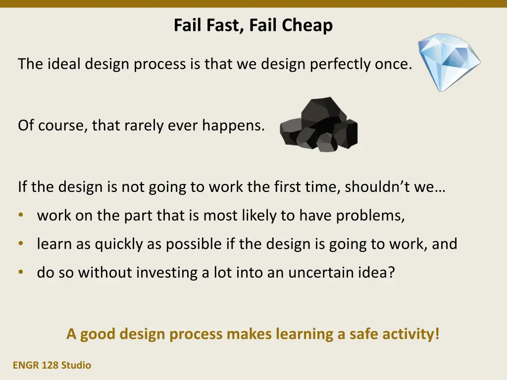
Fail Fast, Fail Cheap The ideal design process is that we design perfectly once. Of course, that rarely ever happens. If the design is not going to work the first time, shouldn t we work on the part that is most likely to have problems, learn as quickly as possible if the design is going to work, and do so without investing a lot into an uncertain idea? A good design process makes learning a safe activity! ENGR 128 Studio
Design Studio Week 4 Today you will: Evaluate and improve the RC circuit design from last week Design and model your own RLC circuit Learn about resonance and natural frequency Review the rubric for technical reports Assignments: Exercise worksheet for RLC circuit design and analysis Project 1 technical report ENGR 128 Studio
Project 1 Review Improve Last week you designed, built, and tested an RC filter circuit. Did it work, i.e. did it meet the requirements? Why not? ENGR 128 Studio
Project 1 Requirements Ask Recall the filter requirements: ???? ??? Magnitude ratio of the output to the input, which depends on the frequency At lower frequencies, we want the output magnitude almost the same as the input. This region is the passband. 1.2 1.0 0.8 At higher frequencies, we want the output magnitude close to zero. This region is the stopband. 0.1 frequency 2.0 kHz 4.0 kHz 6.0 kHz 8.0 kHz 10.0 kHz ENGR 128 Studio
Project 1 Redesign Imagine Let s see if we can improve the performance of the circuit. Since inductors and capacitors alone with a resistor don t work, let s investigate what happens if we use both at the same time. ??= ??? Using impedances: ??= ? ???? ??= ENGR 128 Studio
Project 1 Redesign Plan How can we choose good values of L and C for our design? At frequencies ? 2 kHz (passband region) At frequencies ? 10 kHz (stopband region) ?? ?? ?? ?? We want ?? = ?? somewhere with 2 kHz < ? < 10 kHz. ENGR 128 Studio
Concept Review Resonance So what happens to the inductor and capacitor when ?? = ??? 1 That means ?? = ?? 1 and ??+ ??= ??? + ???= 0! So ??+ ??= ? ??+ ?? = 0, but are ??= 0 and ??= 0? No, they are just opposite of each other The amplitudes are equal Signals are 180 out of phase ENGR 128 Studio
Concept Review Resonance 1 The frequency ? = the resonant frequency, or the natural frequency. ??at which ??+ ??= 0 is called The voltages ?? and ?? actually can become quite large in this case. The tendency to amplify signals at the natural frequency is called resonance. Using Resonance to Break a Wine Glass https://www.youtube.com/watch?v=BE827gwnnk4 ENGR 128 Studio
Project 1 Redesign Plan How can we choose a good value of R for our design? If R is too big, ?? = ?? around 2 kHz and ???? < ???. If R is too small, ???? gets very large near the natural frequency. Write the equations or test some values in Multisim to choose R. ENGR 128 Studio
Project 1 Modeling and Test Create Follow along with the worksheet to build a working version of your circuit design in Multisim with your team. Your instructor is here to help answer guiding questions and troubleshoot any problems that your team identifies. ENGR 128 Studio
Project 1 Technical Report Project 1 features your first technical report. Because this is the first time you will be capturing the entire design, the report will be treated mostly as a learning opportunity. At a top level, the report can be viewed as an account of: What you planned and decided (Methods) What you did and what you learned (Results) What you think you should do next (Conclusions) The report should also include a cover page and references and appendices as needed. Let s review the rubric and example report posted on the Studio website. ENGR 128 Studio
Project 1 Methods Imagine Plan Ask The Methods section covers the Ask, Imagine, and Plan phases. For this project, you should include: The project requirements The RLC circuit design you are using this week The final values of any resistors, capacitors, and inductors ENGR 128 Studio
Project 1 Results Create Test The Results section covers the Create and Test phases. For this project, you should include: The Multisim model you developed A table of your point measurements in Multisim The frequency plot of your circuit magnitude ratio from Multisim A check of the performance versus the requirements ENGR 128 Studio
Project 1 Conclusions Improve The Conclusions section covers the Improve phase. For this project, you should include (as bullet points): Some valuable things you learned about the circuit along the way If you met the requirements, a few steps on getting the design to the next version (e.g. prototyping, more measurements) If you didn t meet the requirements, some steps on how to go back and specifically change the design to improve it ENGR 128 Studio
Project 1 Report Scope Next week we will do some prototyping and hands on measurement of our RLC filter design. Your project report only needs to cover the project work and development through this week (Week 4). The exercises we do next week (Week 5) do not need to be included in the Project 1 report. ENGR 128 Studio
Week 4 Assignments Exercise Complete the Week 4 worksheet handed out earlier. Follow the directions to evaluate the RLC circuit design. Submit the completed worksheet at the start of the next Studio. Project 1 Report Draft a technical report by following the rubric posted online. Submit the completed report at the start of Week 6 Studio. Exam 1 is during Lab of Week 6. Since the Project 1 report doesn t cover the material next week, try to complete most or all of the report this week. Questions after Studio? Email your instructor or go to office hours. ENGR 128 Studio