Innovative Homeostatic Environment Chamber Design Details
Explore the cutting-edge design of a homeostatic environment chamber equipped with essential sensors and controllers to maintain precise environmental conditions. Detailed conceptual designs, functional decompositions, and design criteria are presented along with variant concepts for temperature sensors and controllers.

Download Presentation

Please find below an Image/Link to download the presentation.
The content on the website is provided AS IS for your information and personal use only. It may not be sold, licensed, or shared on other websites without obtaining consent from the author. If you encounter any issues during the download, it is possible that the publisher has removed the file from their server.
You are allowed to download the files provided on this website for personal or commercial use, subject to the condition that they are used lawfully. All files are the property of their respective owners.
The content on the website is provided AS IS for your information and personal use only. It may not be sold, licensed, or shared on other websites without obtaining consent from the author.
E N D
Presentation Transcript
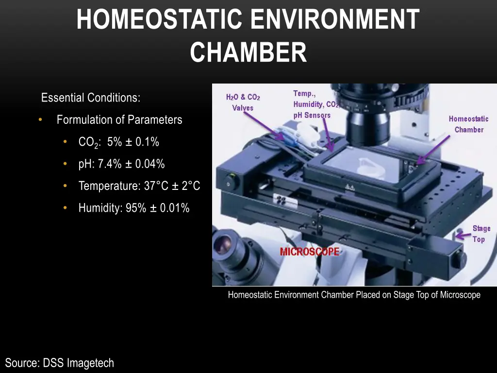
HOMEOSTATIC ENVIRONMENT CHAMBER Essential Conditions: Formulation of Parameters CO2: 5% 0.1% pH: 7.4% 0.04% Temperature: 37 C 2 C Humidity: 95% 0.01% Homeostatic Environment Chamber Placed on Stage Top of Microscope Source: DSS Imagetech
CONCEPTUAL DESIGN Homeostatic Environment Chamber Temperature Sensor Humidity Sensor pH Sensor CO2 Sensor Controller
FUNCTIONAL DECOMPOSITION Sensors Display System Control System Chamber Source
CONCEPT GENERATION Function Sub-Function Chamber Lid Plexiglass Windows (Top/Bottom) Gasket CO2 Valve Water Inlet Insulation Sensors Temperature CO2 pH Humidity Control System Temperature Controller CO2 Controller Microcontroller Data Collecting Output Source Power On/Off Peltier Coolant Display System Temperature CO2 pH Humidity
SUB-SUB FUNCTION OF CONTROLLER Temperature Controller Block Diagram
DESIGN CRITERIA Sensitivity Range Accuracy Cost Design Criteria Temperature Sensors Weighting Matrix Score = Row Sum Sensitivity Range Accuracy Cost Weight. X 5 3 1 9 0.25 Sensitivity 1 X 1 1 3 0.08 Range 3 5 X 3 11 0.31 Accuracy 3 5 5 X 13 0.36 Cost 36 1 Total number of comparisons = Sum of Scores
CONCEPT VARIANTS Concept Variance Ranking With Respect To Sensitivity ThermistorScore = Row Normal Score Sensitivity Thermocouple RTD Sum X 3 1 4 0.22 Thermocouple 3 X 1 4 0.22 RTD 5 5 X 10 0.56 Thermistor 8 8 2 18 1 Column Sum Concept Variance Ranking With Respect To Range ThermistorScore = Row Normal Score Range RTD Thermocouple Sum X 2 1 3 0.17 Thermocouple 4 X 1 5 0.28 RTD 5 5 X 10 0.56 Thermistor 9 7 2 18 1 Column Sum
CONCEPT VARIANTS Concept Variance With Respect To Accuracy Score = Row Sum Normal Score Accuracy RTD Thermistor Thermocouple X 1 3 4 0.22 Thermocouple 5 X 3 8 0.44 RTD 3 3 X 6 0.33 Thermistor 8 4 6 18 1 Column Sum Concept Variance With Respect To Cost Score = Row Sum Normal Score Cost RTD Thermistor Thermocouple X 3 3 6 0.33 Thermocouple 3 X 1 4 0.22 RTD 3 5 X 8 0.44 Thermistor 6 8 4 18 1 Column Sum
SELECTION PROCESS Thermistor is the Winner! -100 C to 150 C Negative Temperature Coefficient Highly Sensitive 59 Selection Process of Temperature Sensors Sensitivity Range Accuracy Cost Score 0.05 0.01 0.07 0.12 0.26 Thermocouple 0.05 0.07 0.14 0.08 0.34 RTD 0.14 0.05 0.10 0.16 0.45 Thermistor
DRAWINGS 208mm x 110mm x 25mm