Innovative Negative Voltage Bias Generator for ePIC Detector Systems
Explore the cutting-edge Negative Voltage Bias Generator (NVBG) developed for ePIC Collaboration meeting, designed to bias substrates of EIC detectors like MAPS and AstroPix. Learn about the design specifications and unique features of the NVBG in enhancing detector performance and functionalities. Discover the importance of substrate bias voltage for pixel threshold and noise distributions in sensor technologies.

Download Presentation

Please find below an Image/Link to download the presentation.
The content on the website is provided AS IS for your information and personal use only. It may not be sold, licensed, or shared on other websites without obtaining consent from the author. If you encounter any issues during the download, it is possible that the publisher has removed the file from their server.
You are allowed to download the files provided on this website for personal or commercial use, subject to the condition that they are used lawfully. All files are the property of their respective owners.
The content on the website is provided AS IS for your information and personal use only. It may not be sold, licensed, or shared on other websites without obtaining consent from the author.
E N D
Presentation Transcript
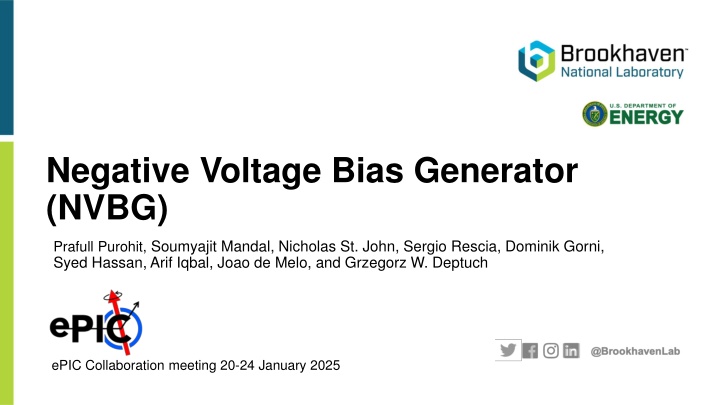
Negative Voltage Bias Generator (NVBG) Prafull Purohit, Soumyajit Mandal, Nicholas St. John, Sergio Rescia, Dominik Gorni, Syed Hassan, Arif Iqbal, Joao de Melo, and Grzegorz W. Deptuch ePIC Collaboration meeting 20-24 January 2025
ePIC SVT Concept Kapton supportsheet Outer Barrel (OB) 2 stave-based layers Sensor EIC-LAS (Serial powered) Bridge PCB Inner Barrel (IB) 3 curved layers Sensor ALICE Mosaix EIC LAS Electron/Hadron Endcaps (EE, HE) 10 disks, 5 on each side of IP Sensor EIC-LAS (Serial powered) Ancillary ASIC 2
Serial powering of EIC-LAS Optical fibers Serial powering has been selected as the powering scheme for ePIC SVT outer barrel & disks Current-based powering scheme - module are powered in series by a constant current Each module is at a different ground potential inside the chain - needs separate substrate bias for each module 3
Need for negative voltage bias generator Required to bias the substrate of the EIC MAPS Prototype has been developed at CERN for the ALICE ITS3 upgrade and demonstrated as the digital pixel test structure (DPTS) Negative voltage bias https://doi.org/10.1016/j.nima.2023.168589 4
Need for negative voltage bias generator (2) Effect of substrate bias voltage (Vsub) is visible in the pixel threshold and noise distributions. Values of -1.2V to -3V are sufficient for the DPTS, but even larger values (up to -6V) may be useful for later versions of the sensor. Negative voltage can be used to bias other chips within the ePIC detector, such as AstroPix. https://doi.org/10.1016/j.nima.2023.168589 5
Design specifications All circuits should run off a single power supply input (=1.2 V) The expected load current is ~200 A, but the negative voltage generator should support currents up to ~1 mA for operational margin Chosen process: X-Fab XT011, which is a HV-PDSOI process with deep trench isolation (DTI) between individual substrate blocks DTI is critical for generating voltages that are negative with respect to the substrate. - Bulk processes do not allow any p-n junctions to be biased negative with respect to the substrate since this always forward-biases a substrate diode The design only uses thin-oxide (1.5 V) transistors to ensure adequate radiation hardness. - This is not a problem for generating large negative voltages as long as individual VGS and VDS values are limited to 1.5 V 6
Negative voltage bias generator MOSFET-based charge-pump circuit Dickson-style RF signal is fed in parallel DC voltage across each capacitor equals VOUT, limiting the maximum output voltage Output impedance increases less rapidly since the capacitors are in parallel Specification Value Voltage range 0 to -6 V Current capacity 1 mA Voltage ripple < 0.1 mV Dickson charge pump 7
RFn Transistor-based charge pump circuit Inverting positive voltages to negative ones requires a switching circuit (AC-DC converter or rectifier) VL VH The four-transistor cell is an efficient CMOS rectifier RF input signal is differentially injected between RFp and RFn DC output signal builds up between VL and VH Flipping input/output DC terminals allows use either as a positive or negative charge pump RFp Use of Deep Trench Isolation (DTI) allows the negative output voltage (VL) to go below the substrate potential (assumed to be ground) Auxiliary diode between VL and VH acts as a passive rectifier that ensures initial start-up https://www.klayout.de/forum/discussion/2390/lvs-soi-isolation Far field RF power extraction circuits and systems Soumyajit Mandal Diss. Massachusetts Institute of Technology, 2004 8
Transistor-based charge pump circuit (2) VNEG Voltage Controlled Oscillator RF Driver Charge Pump No-load DC output voltage is ~2VRF (i.e., the differential RF drive) RFP RFP RFP VNEG VRF Multiple four-transistor cells can be connected in series to generate larger DC output voltages. VH VL VH VL VH VL RFN RFN RFN Topology resembles a Dickson charge pump 9
Transistor-based charge pump circuit (2) VNEG Voltage Controlled Oscillator RF Driver Charge Pump Provides sufficient drive strength to distribute RF clock across the charge-pump Input - 4-bit control (thermometer coded) - RF clock (100 800 MHz, 1.2V) RF driver split into 16 identical branches - Provides coarse control over output voltage - Reduces the required control range of the feedback loop 10
Transistor-based charge pump circuit (2) VNEG Voltage Controlled Oscillator RF Driver Charge Pump Simple ring VCO using current-starved inverters to adjust the RF drive frequency Input - Enable/Pause - Coarse digital control + fine analog control Output - RF clock (100 800 MHz, 1.2V) Allows the oscillation frequency range to be adjusted to ensure a monotonic response BUT, how to control the output? We need to make sure VNEG is equal to the desired PSUB voltage 11
Closed-loop regulator design VNEG Voltage Controlled Oscillator RF Driver Charge Pump Control loop to make sure VNEG is equal to the desired PSUB voltage Multiple control mechanisms: - RF drive amplitude, VRF - RF frequency, fRF - Load current, IL - RF duty cycle, D RF frequency control relies on the fact that the impedance of the pump capacitors is ZP = 1/(j CP). - Results in a non-monotonic control function due to increased losses at high frequencies due to rise/fall times and device/layout parasitics. Maximum efficiency occurs in the 500-600 MHz range. - Circuit implementation is straightforward; chosen for this design 12
Top-level architecture Voltage Controlled Oscillator VNEG RF Driver Charge Pump (main) Charge Pump (aux) Offset Generator RF Driver Voltage divider 20:1 -1.2 V Clock Generator ( SC_Clock ) + 3 V/V A Integrator + Monitor-out (8-bit) Setpoint (8-bit) DAC ADC Inverting circuit needed for closed-loop operation of the negative voltage regulator - Converts the negative output voltage to positive form, thus allowing it to be regulated Blocks completed to date 13
Top-level architecture Voltage Controlled Oscillator VNEG RF Driver Charge Pump (main) Charge Pump (aux) Offset Generator RF Driver Voltage divider 20:1 -1.2 V Clock Generator ( SC_Clock ) + 3 V/V A Integrator + Monitor-out (8-bit) Setpoint (8-bit) DAC ADC A voltage divider (20:1) to ensure the negative input voltage is below one diode drop (< 300 mV) Blocks completed to date 14
Top-level architecture Voltage Controlled Oscillator VNEG RF Driver Charge Pump (main) Charge Pump (aux) Offset Generator RF Driver Voltage divider 20:1 -1.2 V Clock Generator ( SC_Clock ) + 3 V/V A Integrator + Monitor-out (8-bit) Setpoint (8-bit) DAC ADC A switched-capacitor (SC) amplifier that provides accurate voltage gain (equal to 3 in this case) Blocks completed to date 15
Top-level architecture Voltage Controlled Oscillator VNEG RF Driver Charge Pump (main) Charge Pump (aux) Offset Generator RF Driver Voltage divider 20:1 -1.2 V Clock Generator ( SC_Clock ) + 3 V/V A Integrator + Monitor-out (8-bit) Setpoint (8-bit) DAC ADC Current mirror to provide an input voltage offset, which ensures that the output of the SC amplifier stays within its range (0.2V 1V) Blocks completed to date 16
Top-level architecture Voltage Controlled Oscillator VNEG RF Driver Charge Pump (main) Charge Pump (aux) Offset Generator RF Driver Voltage divider 20:1 -1.2 V Clock Generator ( SC_Clock ) + 3 V/V A Integrator + Monitor-out (8-bit) Setpoint (8-bit) DAC ADC The offset current mirror is biased by a single-stage auxiliary charge pump that generates -1.2V Blocks completed to date 17
Top-level architecture Voltage Controlled Oscillator VNEG RF Driver Charge Pump (main) Charge Pump (aux) Offset Generator RF Driver Voltage divider 20:1 -1.2 V Clock Generator ( SC_Clock ) + 3 V/V A Integrator + Monitor-out (8-bit) Setpoint (8-bit) DAC ADC Final element required to close the feedback loop Multiple signed inputs supported via summation at the virtual ground node - Input 1 (+): Reference voltage input (from external DAC) - Input 2 (+): Offset cancellation voltage (VOFF = IOFF*RFB where IOFF is a copy of the current used to create the original offset) - Input 3 (-): Feedback voltage from the switched-capacitor amplifier Blocks completed to date 18
Summary: Closed-loop regulator with FM Closed-loop regulator - Feedback path sets control voltage, Vc, of the VCO Fixed auxiliary charge pump frequency - Fixed at 500 MHz since its output voltage does not need to be adjusted Voltage Controlled Oscillator VNEG RF Driver Charge Pump (main) Offset Generator RF Driver Charge Pump (aux) Voltage divider 20:1 -1.2 V Clock Generator ( SC_Clock ) + RF driver and pump capacitors are split into 16 identical branches - Provides coarse control over the output voltage, thus reducing the required control range of the feedback loop - Used thermometer coding for robustness to single- event upsets 3 V/V A Integrator + Monitor-out (8-bit) Setpoint (8-bit) DAC ADC Nominal values: - RF frequency = 500 MHz - SC clock frequency = 1 MHz 19
Simulation of the closed-loop regulator Drive strength = 16, VREF = 5 x (3/20) V = 0.75 V, should produce -5V, RL = 25 k Output voltage transient looks fine but has overshoot due to the high initial value of Vc If required, Vc can be reset at startup to prevent overshoot 20
Simulation of the closed-loop regulator Drive strength = 4, VREF = 4 x (3/20) V = 0.6 V, should produce -4V, RL = 25 k 21
Simulation of the closed-loop regulator Drive strength = 2, VREF = 3 x (3/20) V = 0.45 V, should produce -3V, RL = 25 k 22
Simulation of the closed-loop regulator Drive strength = 1, VREF = 1.5 x (3/20) V = 0.225 V, should produce -1.5V, RL = 25 k 23
Simulation of the closed-loop regulator Drive strength = 1, VREF = 1 x (3/20) V = 0.15 V, should produce -1V, RL = 25 k SC clock frequency was reduced by 2x (to 500 kHz) to reduce loop bandwidth and thus improve the phase margin 24
Corner simulations X-FAB design kits include the following model variants: tm - typical mean - middle of process tolerances wp - worst case power (fast) Vt min, Id max, Rmin, Cmin ws - worst case speed (slow) Vt max, Id min, Rmax, Cmax wo - worst case one (Ron NMOSmin , Ron PMOSmax) wz - worst case zero (Ron NMOSmax , Ron PMOSmin ) PVT corners: MOS: tm, wp, ws, wo, wz CAP: tm, wp, ws Temp: -20C, +85C Supply: 1.08 V, 1.2 V, 1.32 V 25
Corner simulations (open-loop charge pump) Important to have programming interface to correct variations in output voltage! 1.08V 1.20V 1.32V 26
Corner simulations (complete regulator) Desired output voltage = -1.5 V, RL = 25 k Corners: tm, wp, ws, wo, wz 27
Corner simulations (complete regulator) Desired output voltage = -1.5 V, RL = 25 k Corners: VDD (high) = 1.3 V VDD (nominal) = 1.2 V VDD (low) = 1.1 V 28
Complete layout Aux. 5-stage charge pump charge pump I2C block RF Driver RF Driver 530 m Feedback control loop 1130 m * Size (not including the I2C block) 29
Pre and post-layout simulations Open-loop charge pump, no load -5.76V -5.53V 30
Pre and post-layout simulations NVBG pre-layout simulation NVBG post-layout simulation (woRC) 31
Verification Verification Status Open-loop simulation Pre-layout, closed-loop simulation Post-layout, closed-loop simulation Corner simulation Load response Ripple on the output (Vneg below 500 uV) Under assessment 32
Design review Reviewed: Design and components of the NVG Simulation test benches and performance Floorplan and layout entry Discussed: Start-up sequence in current DAC Radiation hardness Corner simulations Responded to all items https://indico.bnl.gov/event/25455/ 33
Design of MPW1 3.2 mm Contents: CML SLDO pre-regulator from LBL transceiver Negative voltage generator (NVG) SLDO pre-regulator 2.9 mm Test devices Transistor test structures Number of pads = 109 Pad pitch = 100 m Tapeout prepared for November 2024 Negative Voltage Generator 34
Test structures 1.5V low VT MOSFETs (nelvt, pelvt) - Weff. = 100um, L=150nm - Interdigitation layout to measure leakage - Two copies 1) Minimum DTI enclosure spacing 2) 1.0um DTI enclosure spacing 1.5V low VT MOSFETs (nelvt, pelvt) - W=1u, L=110n - W=1u, L=150n - W=1u, L=500n - W=1u, L=1u 1.5V N-type Varactor mosvc (7u x 7u cell) Bipolar transistors - qpva - qpvb POLY resistor Rpp1 (w=3u and l=20u) 35
Future work Design a voltage DAC to generate the reference voltage, VREF, thus allowing the output voltage to be digitally programmed. Monitoring ADC based on the ER2_BNL_VFM_ADC Interfacing to AncBRAIN Integrating first full prototype of AncASIC Model and simulate impact of single-event transients. If needed, use enclosed layout transistors (ELTs) to improve TID tolerance. 36
Test Plan A summary of required tests for verifying the functionality of the NVBG Test Swept parameter Measurement Output range VREF, load current (IL) Output voltage (Vout), estimate load regulation Line regulation Supply voltage (Vdd) Output voltage (Vout), estimate line regulation Transient response VREF, load current (IL) Output rise time, settling time, and peak overshoot as a function of VREF VREF, load current (IL) for different values of fSC Verify loop stability by changing value of fSC Loop bandwidth Power supply rejection ratio (PSRR) Ripple in supply voltage Amplitude of output ripple vs. ripple frequency Output noise and ripple VREF, load current (IL) Output histogram, peak and rms variability, and frequency spectrum Temperature effects Repeat above tests for different temperatures between 25 C and 85 C Planning to test together with WP2 37
Thank you! 38
Negative voltage regulator Soumyajit Mandal, Prafull Purohit, and Grzegorz W. Deptuch October 28, 2024
Feasibility of duty-cycle control Open-loop charge-pump output, VOUT, as a function of D RF frequency = 500 MHz Load current = 1 mA Control range of 0.1 < D < 0.5 is sufficient in this case However, smaller duty cycles will be required for smaller load currents Problems with generating very short pulses can be avoided by only using D for fine control Coarse control can be obtained by using a switched array to vary the pump capacitance, CP 41
Duty-cycle modulator (DCM) design Based on the DCM design in [1]. Uses matched VCDLs to generate the difference between a fixed (minimum) and variable time delay. Additional logic ensures that the maximum duty cycle is limited to 50%. The initial implementation worked but suffered from unwanted latching in the VCDL delay cells and relatively long propagation delays in the standard-cell DFFs. Design was tweaked to improve performance. For instance, the standard-cell DFFs were replaced with custom TSPC DFFs, which are much faster. Pseudo-differential implementation [1] Djemouai, A., Sawan, M., & Slamani, M. (2000, December). New CMOS integrated pulse width modulator for voltage conversion applications. In ICECS 2000. 7th IEEE International Conference on Electronics, Circuits and Systems (Cat. No. 00EX445) (Vol. 1, pp. 116-119). IEEE. 42
DCM simulation results @500 MHz Adequate duty cycle control range (0.45 to 0.05) for a control voltage range of 0.3-1.2 V Time-domain waveforms versus control voltage, Vc Estimated duty cycle versus Vc 43
Closed-loop regulator with DCM Auxiliary RF driver Integrator added in the feedback path to set the control voltage, Vc, of the DCM Duty cycle of the auxiliary charge pump is kept fixed at 50% since its output voltage does not need to be adjusted RF driver and pump capacitors are split into 8 identical branches Provides coarse control over the output voltage, thus reducing the required control range of the feedback loop Thermometer coding also provides robustness to single-event upsets Nominal values: RF frequency = 500 MHz SC clock frequency = 1 MHz Main RF driver SC clock DCM Main charge pump Voltage driver, anti-alias filter SC integrator SC amplifier Offset voltage generator Auxiliary charge pump 44
Simulation of the closed-loop regulator VREF = 5 x (3/20) V = 0.75 V, should produce -5V Output voltage transient looks OK, but what s this? 45
Simulation of the closed-loop regulator Drive strength = 16, VREF = 5 x (3/20) V = 0.75 V, should produce -5V Detail of the integrator output, i.e., the VCO control voltage 46


")


")
")
")


")
")
")


 design")