Innovative NFC Sensor System Design with TI MSP430FR5969 - ECE 492 Winter Project 2015
"Explore the detailed design and functionality of an NFC sensor system using Texas Instruments MSP430FR5969 in an ECE 492 project. Learn about sensor connections, software flow, challenges, calculations, components, and more for real-time data monitoring via NFC, Bluetooth, and DE0."

Download Presentation

Please find below an Image/Link to download the presentation.
The content on the website is provided AS IS for your information and personal use only. It may not be sold, licensed, or shared on other websites without obtaining consent from the author. If you encounter any issues during the download, it is possible that the publisher has removed the file from their server.
You are allowed to download the files provided on this website for personal or commercial use, subject to the condition that they are used lawfully. All files are the property of their respective owners.
The content on the website is provided AS IS for your information and personal use only. It may not be sold, licensed, or shared on other websites without obtaining consent from the author.
E N D
Presentation Transcript
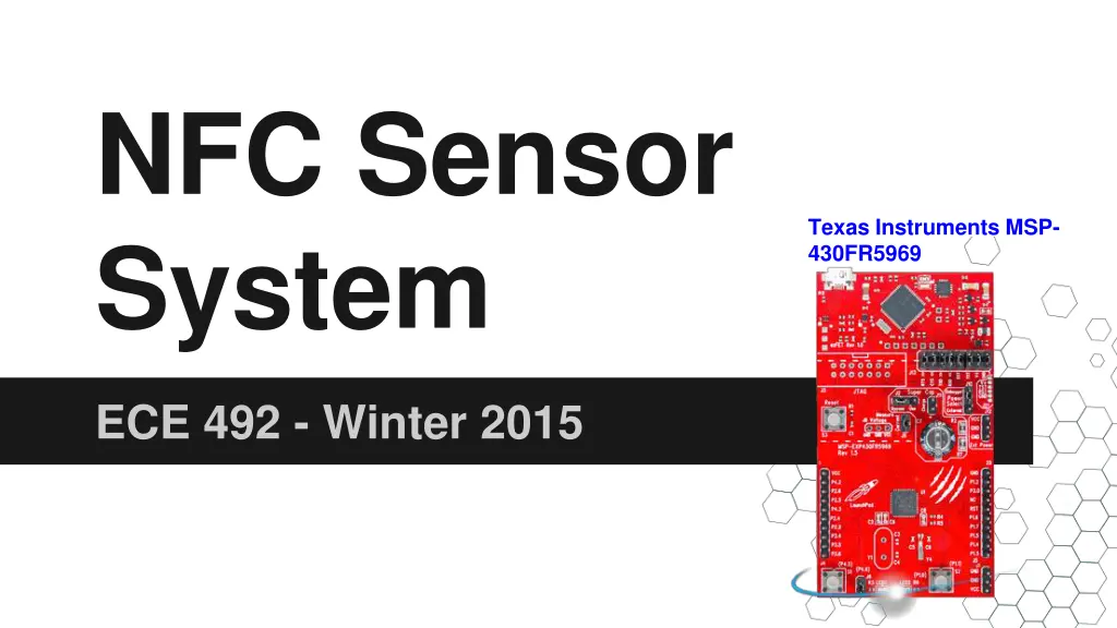
NFC Sensor System Texas Instruments MSP- 430FR5969 ECE 492 - Winter 2015
Group Members Mike Pappas Sensor connections to MCU and NFC Nigel Himmelreich NFC connection to DE0 and Bluetooth Eric Anderson Bluetooth-Android communication, data logging and sensor display application
Functionality Inspired by a disposable Smart Bandage Transmits real time sensor data over NFC Inductively powered via NFC Transfers NFC data to Bluetooth for constant monitoring via DE0 Data logging/display on Android
Design - Sensor Connections As of Feb 8, 2015
Design - Software MCU o Gather sensor data o Package into NDEF (NFC data format) and send DE0 o Read from NFC and log o Send data over Bluetooth Smartphone o Read current sensor data o Display current and past data graphically
Design - Sensor Software Flow Diagram Induction power does not allow for idling Power on -> Initialize -> Perform Read -> Power Off (lose power)
Design - Challenges Induction power - difficult to operate on 100 A. Challenging antenna implementation ( 1mm x 1.8mm Schottky diodes with < 0.4V forward voltage) NFC to DE0 communication - minimal resources available
Design - Calculations Antenna Design where a = (ri + ro)/2 b = ro ri ri = Inner radius of the spiral ro = Outer radius of the spiral N = number of turns Antenna Inductance (fres~ 13.7MHz) Min Typical Max 3.57 H (@ Cint = 38.5 pF) 3.85 H (@ Cint = 35 pF) 4.28 H (@ Cint = 31.5 pF)
Design - Components Thermal sensor and light diode TI MSP430FR5969 MCU TI RF430CL330H NFC Module PN532 NFC Shield DE0 Nano MOD-BT Bluetooth Module Android Device
Code Example - RF430 Read unsigned int Read_Register(unsigned int reg_addr) { TxAddr[0] = reg_addr >> 8; TxAddr[1] = reg_addr & 0xFF; // MSB of address // LSB of address UCB0CTLW1 = UCASTP_1; UCB0TBCNT = 0x0002; UCB0CTL1 &= ~UCSWRST; UCB0CTL1 |= UCTXSTT + UCTR; while(!(UCB0IFG & UCTXIFG0)); // USCI Automatic stop condition // UFCI Byte Counter threshold // Software reset // Start i2c write operation // Wait for TX // Assign Buffer To MSB of Address // Wait for TX // Assign Buffer to LSB of Address // Wait for biyte counter of interupt // I2C read operation // Repeated start // Wait for RX // Assign MSB // Send stop after next RX // Wait for RX // Assign LSB // Ensure stop condition got sent // Software Reset UCB0TXBUF = TxAddr[0]; while(!(UCB0IFG & UCTXIFG0)); UCB0TXBUF = TxAddr[1]; while(!(UCB0IFG & UCBCNTIFG)); UCB0CTL1 &= ~UCTR; UCB0CTL1 |= UCTXSTT; while(!(UCB0IFG & UCRXIFG0)); RxData[0] = UCB0RXBUF; UCB0CTLW0 |= UCTXSTP; while(!(UCB0IFG & UCRXIFG0)); RxData[1] = UCB0RXBUF; while (!(UCB0IFG & UCSTPIFG)); UCB0CTL1 |= UCSWRST; return RxData[1] << 8 | RxData[0]; }
Test Plans Unit Testing o Test sensor data being read to MCU o Test NFC data is being sent from MCU to DE0 o Test Bluetooth data from DE0 to smartphone o Verify logging ability of DE0 and smartphone o Test smartphone app and functionality Integration Testing o Test overval data from sensors to smartphone o Verify correct data logged
Optional features Inductively power the NFC, MCU, & sensors via power from the NFC antenna when communicating with the receiving board Add additional sensors Join the NFC, MCU, & sensors all on one single circuit board with integrated antenna