Insight into IEEE 802.11ba PHY for AMP WUR Implementation
Gain valuable insights into leveraging the IEEE 802.11ba PHY for implementing a Wake-Up Radio (WUR) for Advanced Metering Infrastructure (AMP) in the 2.4 GHz frequency band. Explore PPDU formats, modulation, data rates, and more, with a focus on potential modifications required. Discover the structure of both non-WUR and WUR portions of the PPDU, including their functions and implications.
Download Presentation

Please find below an Image/Link to download the presentation.
The content on the website is provided AS IS for your information and personal use only. It may not be sold, licensed, or shared on other websites without obtaining consent from the author. If you encounter any issues during the download, it is possible that the publisher has removed the file from their server.
You are allowed to download the files provided on this website for personal or commercial use, subject to the condition that they are used lawfully. All files are the property of their respective owners.
The content on the website is provided AS IS for your information and personal use only. It may not be sold, licensed, or shared on other websites without obtaining consent from the author.
E N D
Presentation Transcript
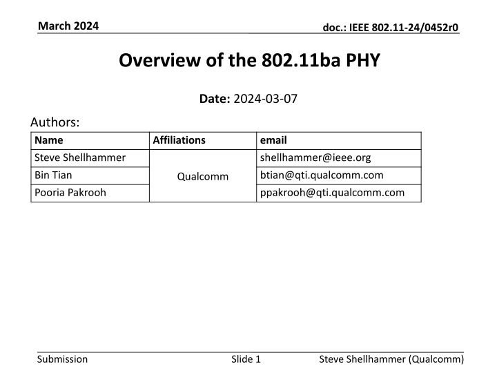
March 2024 doc.: IEEE 802.11-24/0452r0 Overview of the 802.11ba PHY Date: 2024-03-07 Authors: Name Affiliations email Steve Shellhammer shellhammer@ieee.org Bin Tian Pooria Pakrooh btian@qti.qualcomm.com ppakrooh@qti.qualcomm.com Qualcomm Submission Slide 1 Steve Shellhammer (Qualcomm)
March 2024 doc.: IEEE 802.11-24/0452r0 Introduction AMP needs a wake-up radio (WUR) specification There is an opportunity to leverage the 802.11ba PHY, with possibly some modifications, for the AMP WUR, in the 2.4 GHz frequency band. The purpose of this presentation is to give an overview of the 802.11ba PHY so the AMP group can begin discussions on what can be leveraged from the 802.11ba PHY and what might need to be modified Note: 802.11ba supports 2.4 GHz but does not support sub-1GHz operation, so clearly changes will need to be made to 802.11ba to support sub-1GHz frequency bands A description of both the 802.11ba PHY and MAC is available in [1] Submission Slide 2 Steve Shellhammer (Qualcomm)
March 2024 doc.: IEEE 802.11-24/0452r0 Outline PPDU Format Bandwidth Modulation Data Rates Manchester Encoding Sync Field Data Field Symbol Randomization TX Diversity Final Comments Conclusions References Submission Slide 3 Steve Shellhammer (Qualcomm)
March 2024 doc.: IEEE 802.11-24/0452r0 PPDU Format Note: Figures from the standard [2] are used in this presentation The PPDU is divided into the non-WUR Portion and the WUR Portion o Non-WUR Portion: L-STF, L-LTF, L-SIG, BPSK-Mark1, and BPSK-Mark2 o WUR Portion: WUR-Sync and WUR-Data Submission Slide 4 Steve Shellhammer (Qualcomm)
March 2024 doc.: IEEE 802.11-24/0452r0 PPDU Format (non-WUR Portion) non-WUR portion The non-WUR portion (L-STF, L-LTF, L-SIG, BPSK-Mark1, BPSK-Mark2) are OFDM symbol intended to be decoded by Third-Party STAs. The non-WUR portion signals appears to the Third-Party STAs as an 802.11a PPDU and indicates the duration of the PPDU. The Third-Party STAs that hear the non-WUR portion will avoid transmitting during the PPDU duration Submission Slide 5 Steve Shellhammer (Qualcomm)
March 2024 doc.: IEEE 802.11-24/0452r0 PPDU Format (WUR Portion) WUR portion The WUR portion (WUR-Sync and WUR-Data) are Multicarrier On-Off Keying (MC-OOK) modulated fields. There are two versions of the WUR-Sync Fields o 64 s duration, used for high-data rate (HDR) o 128 s duration, used for low-data rate (LDR) The WUR Receiver uses the WUR-Sync field to detect the PPDU, identify the data rate, and perform timing alignment The WUR-Data field carries the data at either the high or low data rate Submission Slide 6 Steve Shellhammer (Qualcomm)
March 2024 doc.: IEEE 802.11-24/0452r0 Bandwidth The non-WUR portion is a standard 20-MHz OFDM bandwidth o There is also an optional 80-MHz bandwidth The WUR portion bandwidth is 4 MHz The choice of the WUR portion bandwidth is a trade-off between several factors Factors Considered in selecting Bandwidth of WUR Portion Affect on Choice of WUR Bandwidth Regulations In some regulatory domains there is a PSD limit leading to an allowed TX power increase with wider bandwidth [3]. Receiver Filtering for Adjacent Channel Interference The WUR Receiver needs to be low-complexity and hence its filtering will be poorer than a regular receiver. To get desired Adjacent Channel Rejection, the TX signal needs to be less than the 20-MHz channel bandwidth. Overall Receiver power consumption Wider TX bandwidth requires wider bandwidth baseband signals leading to an increase in Receiver power consumption Submission Slide 7 Steve Shellhammer (Qualcomm)
March 2024 doc.: IEEE 802.11-24/0452r0 Modulation To enable a WUR Receiver implementation with very low power consumption, the Task Group agreed to use on-off keying (OOK) The receiver does not require a low phase noise oscillator An envelop detector can be used for low complexity There are many research papers demonstrating low power wake-up receivers using OOK With standard single-carrier OOK the TX bandwidth is set by the OOK symbol rate, and as we will explain later, a low symbol rate has advantages for the WUR Submission Slide 8 Steve Shellhammer (Qualcomm)
March 2024 doc.: IEEE 802.11-24/0452r0 Modulation (cont.) In order to reuse a standard OFDM transmitter with small changes it was proposed to apply OOK to the OFDM waveform The 4 s OFDM symbol was selected The TX implementation to transmit OOK based on this OFDM symbol can be accomplished by either sending the OFDM symbol or transmitting zeros during that 4 s period It turns out there was a need for a 2 s OOK for the WUR-Sync field and the HDR WUR-Data field. o In that case half of the 4 s Symbol is used. Submission Slide 9 Steve Shellhammer (Qualcomm)
March 2024 doc.: IEEE 802.11-24/0452r0 Modulation (cont.) There are additional benefits to this multicarrier on-off keying (MC-OOK) waveform beyond the ease of TX implementation With single-carrier OOK the TX bandwidth is set by the OOK symbol rate, and as we will explain later, a low symbol rate has advantages for the WUR With this style of OOK we can have a wider bandwidth than the bandwidth based on the symbol rate To obtain a 4 MHz bandwidth 13 subcarriers are used, and the other subcarriers are null This is a much larger bandwidth than would be obtained if a single carrier OOK was used with this symbol rate Submission Slide 10 Steve Shellhammer (Qualcomm)
March 2024 doc.: IEEE 802.11-24/0452r0 Data Rates The Task Group decided on two data rates o Low Data Rate (LDR) = 62.5 kb/s o High Data Rate (HDR) = 250 kb/s The LDR has better range given it operates at a lower SNR. o It can operate at 6 dB lower than the HDR. The HDR has the advantage of a shorter PPDU duration. The LDR is mandatory and the HDR is optional. Submission Slide 11 Steve Shellhammer (Qualcomm)
March 2024 doc.: IEEE 802.11-24/0452r0 Manchester Encoding In OOK without a line code (like Manchester encoding) the receiver needs to set a threshold between the receive level of the On and Off symbols, in order to decode. With Manchester encoding logical bits are encoded by an On symbol followed by an Off symbol or an Off symbol followed by an On Symbol To decode a bit, the receiver can subtract the power of the first symbol from the power of the second symbol and comparing to zero. Hence, with Manchester encoding the receiver does not need to determine the optimum threshold between On and Off receive symbols o This simplifies the WUR decoder Submission Slide 12 Steve Shellhammer (Qualcomm)
March 2024 doc.: IEEE 802.11-24/0452r0 Manchester Encoding (Cont.) Below we see the reception of either a Manchester encoded Logical Zero or Logical One The receiver only needs to compare the received energy in the two symbols to decode Note, this does require two symbols to transmit one logical bit Submission Slide 13 Steve Shellhammer (Qualcomm)
March 2024 doc.: IEEE 802.11-24/0452r0 WUR-Sync Field The first part of the WUR Portion of the PPDU is the Sync field As the name implies, it enables the WUR Receiver to synchronize to the transmitted signal It also allows for packet detection There are two possible lengths of the Sync field o 64 s duration, used for high-data rate (HDR) o 128 s duration, used for low-data rate (LDR) The Task Group decided to not include a signal (SIG) field, which is where in other 802.11 standards the data rate, or modulation and coding scheme (MCS) is transmitted o This is intended to simplify the PPDU format So, the Sync field is used to signal whether HDR or LDR is used in the Data field Submission Slide 14 Steve Shellhammer (Qualcomm)
March 2024 doc.: IEEE 802.11-24/0452r0 WUR-Sync Field (cont.) The Task Group decided to use 2 s symbols in the Sync field instead of 4 s symbols The reason for this is that for a given duration, more short symbols can be fit into the specified duration For example, in a 64 s duration: o If the symbol duration is 2 s then 32 symbols can be used o If the symbol duration is 4 s only 16 symbols can be used Having more symbols makes it possible to design a more robust Sync field Submission Slide 15 Steve Shellhammer (Qualcomm)
March 2024 doc.: IEEE 802.11-24/0452r0 WUR-Sync Field (cont.) For the HDR the Sync field is specified as the bit sequence ?, which is the logical complement of the sequence ? With 1 indicating an On symbol and 0 indicating an Off symbol For the LDR the Sync field is specified as the bit sequence ??, which is the concatenation of two copies of ? With 1 indicating an On symbol and 0 indicating an Off symbol Submission Slide 16 Steve Shellhammer (Qualcomm)
March 2024 doc.: IEEE 802.11-24/0452r0 WUR-Sync Field (cont.) Since the HDR and the LDR use ? and ? respectively, the WUR receiver can be built that is unlikely to confuse an HDR and a LDR WUR-Sync field Simulations were performed by the Task Group to show that reliable packet detection, data rate identification, and timing recovery can be performed It was also shown that the Sync field is more robust than the Data field, so the receiver sensitivity is determined by the Data field processing Submission Slide 17 Steve Shellhammer (Qualcomm)
March 2024 doc.: IEEE 802.11-24/0452r0 WUR-Data field The HDR has a data rate of 250 kb/s meaning that the bit duration is 4 s A pair of 2 s symbols are used along with Manchester encoding Submission Slide 18 Steve Shellhammer (Qualcomm)
March 2024 doc.: IEEE 802.11-24/0452r0 WUR-Data field The LDR has a data rate of 62.5 kb/s meaning that the bit duration is 16 s Four 4 s symbols are used It consists of Manchester encoding and repetition coding Submission Slide 19 Steve Shellhammer (Qualcomm)
March 2024 doc.: IEEE 802.11-24/0452r0 Symbol Randomization It was pointed out in the Task Group, that if the same ODFM waveform is used for each OOK symbol, then the spectrum of the PPDU will have spectral lines in the frequency domain Figure from [4] Submission Slide 20 Steve Shellhammer (Qualcomm)
March 2024 doc.: IEEE 802.11-24/0452r0 Symbol Randomization (cont.) A combination of two methods were used to address this issue o Pseudo random multiplication by +? or ? o Pseudo random cyclic shift diversity (CSD) applied to OFDM waveform A common linear feedback shift register (LFSR) is used to generated the random bit sequence This was shown to eliminate the spectral lines and improve the flatness of the spectrum Submission Slide 21 Steve Shellhammer (Qualcomm)
March 2024 doc.: IEEE 802.11-24/0452r0 Transmit Diversity The WUR Transmitter is often an access point Typical access points have multiple antennas To avoid unintentional beamforming cyclic shift diversity (CSD) is applied to the TX antennas Tables of recommended CSD values are provided in the standard Task Group simulations were performed to compare the packet error rate for different number of TX antennas The simulations were performed for both an AWGN channel and Channel Model D Submission Slide 22 Steve Shellhammer (Qualcomm)
March 2024 doc.: IEEE 802.11-24/0452r0 Final Comments Not including a Signal (SIG) field in the WUR Portion had two effects 1. Different Sync fields were needed to indicated the data rate: HDR or LDR. 2. There was no PHY field to indicate the length of the Data field, so that needed to be done in the MAC. This is a bit of a cross-layer violation. Submission Slide 23 Steve Shellhammer (Qualcomm)
March 2024 doc.: IEEE 802.11-24/0452r0 Conclusions and Next Steps Conclusions o An overview of the 802.11ba PHY has been provided to the AMP group, to stimulate discussion on the AMP WUR design Next Steps o The Task Group can identify in what ways the 802.11ba satisfies the AMP requirements and in what ways modifications needed. Submission Slide 24 Steve Shellhammer (Qualcomm)
March 2024 doc.: IEEE 802.11-24/0452r0 References 1. Steve Shellhammer, Alfred Asterjadhi, and Yanjun Sun, IEEE 802.11ba: Ultra-Low Power Wake-up Radio Standard, Wiley-IEEE Press, 2023 2. IEEE Std 802.11ba, IEEE Standard for Local and Metropolitan Area Networks: Wireless LAN Medium Access Control (MAC) and Physical Layer (PHY) Specifications. Amendment: Wake-up Radio Operation, 2021 3. Steve Shellhammer and Bin Tian, Regulations and Noise Figure Impact on SNR, IEEE 802.11-17/365r0, March 2017 4. Steve Shellhammer, Bin Tian, and Richard van Nee, WUR Power Spectral Density, IEEE 802.11-18/824r0, May 2018 Submission Slide 25 Steve Shellhammer (Qualcomm)

