Insight into Optical and X-ray Diffraction for Fibre Structures
"Learn how optical and X-ray diffraction techniques provide valuable insights into the internal structure of fibers, including details on spacing, crystal orientation, and crystallite size. Discover the significance of diffraction patterns in studying the fine details of fiber structure."

Download Presentation

Please find below an Image/Link to download the presentation.
The content on the website is provided AS IS for your information and personal use only. It may not be sold, licensed, or shared on other websites without obtaining consent from the author. If you encounter any issues during the download, it is possible that the publisher has removed the file from their server.
You are allowed to download the files provided on this website for personal or commercial use, subject to the condition that they are used lawfully. All files are the property of their respective owners.
The content on the website is provided AS IS for your information and personal use only. It may not be sold, licensed, or shared on other websites without obtaining consent from the author.
E N D
Presentation Transcript
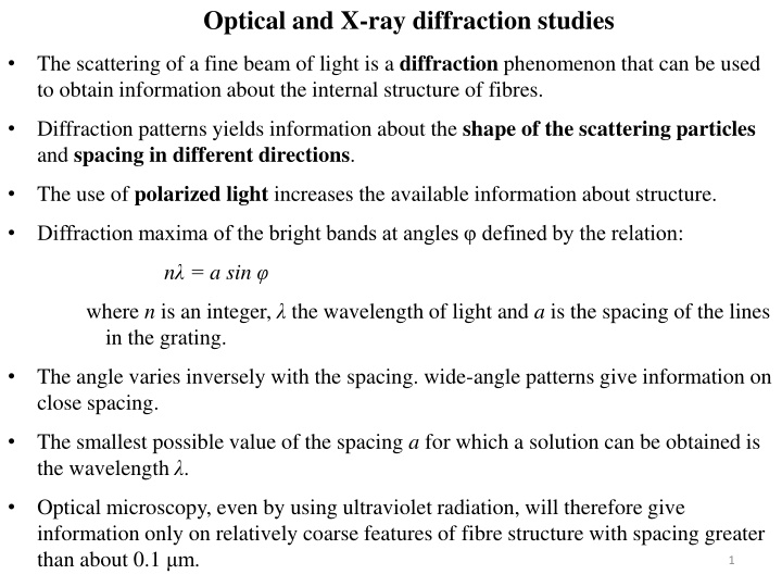
Optical and X-ray diffraction studies The scattering of a fine beam of light is a diffraction phenomenon that can be used to obtain information about the internal structure of fibres. Diffraction patterns yields information about the shape of the scattering particles and spacing in different directions. The use of polarized light increases the available information about structure. Diffraction maxima of the bright bands at angles defined by the relation: n = a sin where n is an integer, the wavelength of light and a is the spacing of the lines in the grating. The angle varies inversely with the spacing. wide-angle patterns give information on close spacing. The smallest possible value of the spacing a for which a solution can be obtained is the wavelength . Optical microscopy, even by using ultraviolet radiation, will therefore give information only on relatively coarse features of fibre structure with spacing greater than about 0.1 m. 1
X-ray diffraction is a most important tool for the study of fibre structure, 0.1 and 0.5 nm. Narrow-angle diffraction will give information on longer spacing, of the order of 10 100 nm. A crystal can be regarded as made up of layers of atoms, themselves regular in their two-dimensional plan, stacked regularly on top of one another. If a beam of X-rays is directed at a crystal, it is strongly reflected whenever it strikes layers of atoms at an angle , such that: n = 2d sin 2
Sampling Fibre samples: fibres are held mutually parallel and straightened along their fibre axis in a bunch owing to orientation of crystallites, diffraction maxima appears as arcs. Greater the degree of orientation smaller will be arc length. Powder sample: fibres are cut into small pieces like powder and compressed to form pellets. Thus, crystallites are randomly oriented and diffraction maxima is obtained in the form of uniform circles. Radial scanning for powder sample for calculation of crystallinity and crystal size. Ac XRD a primary technique to determine the degree of crystallinity in polymers. Aa ?? 100% ?????????????%= ??+ ?? 4
If the orientation is not completely perfect, one can get reflections over a range of angles, and the spots broaden out into arcs. Smaller the arc length, higher will be the orientation. Radial scanning of the diffraction pattern gives intensity (I) Vs. 2 . 6
Determination of Crystal size ?? ? = ????? Crystal thickness: wavelength, K is a constant close to 0.9. where, B is the half width of the diffraction peak, is the diffraction angle, ? is the Determination of Crystalline orientation Degree of orientation is related to the angle subtended by the arc. The more complete appraisal of the orientation can be made by the measuring the intensity of the arc at selected intervals. Intensity can be plotted against the azimuthal position (?): azimuthal scanning. The shape of the azimuthal scan determines the orientation of crystallites. 7
Hermans orientation function for crystalline orientation, fc, is defined as ??= 1 3 ? 2???2 ?/? ? ?/? ? ? ? ??????? ? = ???2 Where, ? ? ?????? For meridional plane the angle ? has same significance as the azimuthal angle ?. For perfect orientation fc=1, and for perfectly random orientation fc=0 8