Insights into FCCee and CEPC for High-Energy Physics Studies
"Explore the similarities between FCCee and CEPC machines designed as Higgs factories, focusing on the challenges of studying Higgs boson decay and distinguishing interactions. Learn about machine parameters, backgrounds, and Higgs production in these advanced colliders." (313 characters)

Download Presentation

Please find below an Image/Link to download the presentation.
The content on the website is provided AS IS for your information and personal use only. It may not be sold, licensed, or shared on other websites without obtaining consent from the author. If you encounter any issues during the download, it is possible that the publisher has removed the file from their server.
You are allowed to download the files provided on this website for personal or commercial use, subject to the condition that they are used lawfully. All files are the property of their respective owners.
The content on the website is provided AS IS for your information and personal use only. It may not be sold, licensed, or shared on other websites without obtaining consent from the author.
E N D
Presentation Transcript
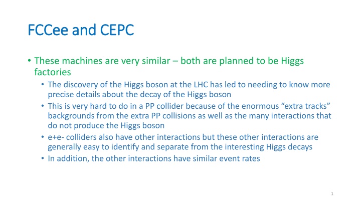
FCCee and CEPC FCCee and CEPC These machines are very similar both are planned to be Higgs factories The discovery of the Higgs boson at the LHC has led to needing to know more precise details about the decay of the Higgs boson This is very hard to do in a PP collider because of the enormous extra tracks backgrounds from the extra PP collisions as well as the many interactions that do not produce the Higgs boson e+e- colliders also have other interactions but these other interactions are generally easy to identify and separate from the interesting Higgs decays In addition, the other interactions have similar event rates 1
Soft bend magnets just before the IP. FCC FCC- -ee rings ee rings Layout of the FCC-ee rings. The rings are 91 km in circumference. CERN is at the top with the LHC touching the in two places near the top of the rings. There is talk of adding two more IRs making a total of 4. 2
FCCee machine parameters FCCee machine parameters The ring is 91 km in circumference. It takes light 0.3 ms to go around the ring (revolution time). The current plan is to have 4 IPs 3
CEPC machine parameters CEPC machine parameters These are the more aggressive machine parameters for the CEPC which includes the possibility of running at the ttbar threshold. 4
Backgrounds at the Z Backgrounds at the Z The various running points for the FCCee mean that there will be very different backgrounds for the various machines At the Z the FCCee (and CEPC) will come close to looking like the B- factory machines Note the high beam currents of 1.4 A (0.8 A for the CEPC) This mode of operation will generate outgassing and force a scrubbing time during the initial running Synchrotron radiation backgrounds should be very low when the beam energy is down to 46 GeV the critical energies will be low The FCCee intends to start at the Z resonance whole the CEPC will start at the Higgs 5
Higgs production Higgs production The Higgs energy (120 GeV/beam) which is slightly below the HH threshold (128 GeV/beam) is because one can make a single Higgs boson together with a Z boson This is due to the fact that the e+e- annihilation can go directly to the Z (the Z has the correct quantum numbers 1 ) and since the Higgs has zero spin, then HH production through pure e+e- annihilation is highly suppressed. However, one does need to get close to the HH threshold before this works very well Recall the plot of e+e- to hadrons The ? and ?+ annihilate into a virtual Z* that can then decay to a standard Z and a Higgs boson. We have to be close to the HH threshold for this interaction to have a good rate. The mass of the Z is 92 GeV so we must have at least 91+125 GeV = 216 GeV total Ecm. 6
Higgs background Higgs background At the Z-Higgs production point, the beam currents are significantly lower (FCCee has 27 mA and CEPC has 17 mA) These numbers are much closer to the currents used in the LEP machine The FCCee will have already scrubbed the beam pipe When the CEPC initially runs here there will be some small amount of scrubbing, but the time required to clean the beam pipe should not be very long Since the CEPC will go down to the Z energy after the Higgs run, they will then go to a high beam current configuration and will have to re-scrub the beam pipe at that time In either case, backgrounds from beam-gas scattering should not be very high at the Z-Higgs energy 7
Higgs and ttbar SR backgrounds Higgs and ttbar SR backgrounds The higher beam energies (120 GeV) will raise the critical energy of the SR both in the final focus quads and in local bend magnets SR backgrounds will increase significantly unless the masking scheme can thoroughly protect the central chamber This is probably the place where the SR masking should be optimized The ttbar energy set point will be the most difficult to fully shield the central beam pipe from SR This is because, at this beam energy, the critical energy of the particles as they are focused in the final focusing magnets is highest since the magnetic strength of the final focus magnets is also highest 8
ttbar SR ttbar SR Based on experience at LEP, the FCCee design has placed an upper limit on the critical energy from the last bend magnet to be no more than 100 keV This, of course, is set for the highest energy: the ttbar threshold (182.5 GeV/beam) The ttbar beam currents are the lowest (5.0 mA for the FCCee and 3.3 mA for the CEPC) so the number of SR photons will also be the smallest and this helps a lot Detectors can always take some amount of background level so if the hit rate from SR is low enough then it no longer is considered a problem 9
FCCee IR FCCee IR Vertically expanded view of the IR. There is only one SR mask in this design, and it is used to protect the central beam pipe from the SR fan coming from the last bend magnet 100 m away. The following slides show this in more detail. This view is from the inside of the ring looking out. Mask tip 10
SR details for SR details for the FCCee the FCCee A rotated view with the incoming beam pipe along the Z axis or X axis of the plot. Note how the central chamber (the read marked sections) is now fairly well protected on the bottom of the picture but the top part is now exposed to upstream SR. Mask tip This is the exact same situation for the other incoming beam. The positive X side of the chamber is again exposed to upstream SR. 11
FCCee bend SR FCCee bend SR These numbers refer to a ttbar beam energy of 175 GeV and 6.625 mA. Each 42 W segment of the fan corresponds to a 6.9 m length of the magnet. Highly distorted or anamorphic picture A concern for this large machine is specular reflection from the far upstream beam pipe wall (ala an LCLS or x-ray mirror). The incident angle is small which means specular reflection is certainly a possibility. Mask tip 42W 42W Specular reflection can be a real concern because it is reasonably efficient in reflecting x-rays (it can be >70% and sometimes even higher). 0.46 mrad incident angle. 100 keV critical energy at the ttbar by design Nearly half of the photons in this fan are below 0.1 Ecrit = 10 keV and 80% are below 0.5 Ecrit = 50 keV. 12
Possible remedies Possible remedies One can roughen up the beam pipe surface removing the mirror like effect One can install a series of small mask tips all along the 100 m of beam pipe The small masks would be such as to ensure that no photon hits the beam pipe wall and only strikes the upstream mask surface This criteria sets the height and the spacing between tips One can try to install a mask closer to the central chamber that would mask the pipe This may be very difficult as the mask tip may have to either come very close to or actually intrude into the BSC before it can shield the pipe It may be that the rate on the beam pipe is low enough? This we can estimate this using some assumptions This is currently an ongoing study the CEPC machine will have the same issue 13