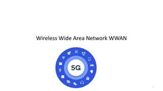
Insights into GSM Evolution and Architecture
Explore the evolution of GSM technology from its inception to the present day, including the GSM 900, 1800, and 1900 bands. Learn about the components of the GSM system architecture and the key role of mobile phones, antennas, and infrastructure. Gain a comprehensive understanding of GSM and its global impact on mobile communications.

Download Presentation

Please find below an Image/Link to download the presentation.
The content on the website is provided AS IS for your information and personal use only. It may not be sold, licensed, or shared on other websites without obtaining consent from the author. If you encounter any issues during the download, it is possible that the publisher has removed the file from their server.
You are allowed to download the files provided on this website for personal or commercial use, subject to the condition that they are used lawfully. All files are the property of their respective owners.
The content on the website is provided AS IS for your information and personal use only. It may not be sold, licensed, or shared on other websites without obtaining consent from the author.
E N D
Presentation Transcript
MCS: GSM Global System for Mobile Communications
GSM evolution GSM=Global System for Mobile Communications GSM Evolution: 1979 the 900MHz band reserved 1982 Groupe Sp cial Mobile under CEPT (Post &Telecom European Conference) 1988-89 GSM taken over by ETSI (European Telecommunication Standard Institute) 1990-91 Phase 1 recommendations DCS1800 1992 first commercial GSM networks 1995 Phase 2 recommendtions issued 1998 3GPP (3rd Generation Partnership Project)
GSM 900, 1800, 1900 GSM 900: 2 x 25 MHz frequency bands: 890-915 MHz UL, 935-960 MHz DL 124 carriers, 200 kHz each Extended version: 2x35MHz 880-915MHz UL, 925-960MHz DL, 174 carriers, 200kHz each GSM 1800 (Digital Cellular System -DCS) At the request of the UK 2x75MHz frequency bands: 1710-1785 MHz UL, 1805-1880 MHz DL 374 carriers (200kHz/carrier) GSM 1900 (Personal Communication System or PCS1900) North and South American version of DCS 1800 GSM 850 same frequency range like AMPS, D-AMPS, IS-95 (American standards) 824-890MHz UL, 869-894MHz DL, 124x200kHz carriers
Architecture of the GSM system [JS] GSM is a PLMN (Public Land Mobile Network) several providers setup mobile networks following the GSM standard within each country components MS (mobile station) BS (base station) MSC (mobile switching center) LR (location register) subsystems RSS (radio subsystem): covers all radio aspects NSS (network and switching subsystem): call forwarding, handover, switching OSS (operation subsystem): management of the network
Ingredients 1: Mobile Phones [JS] The visible but smallest part of the network!
Ingredients 2: Antennas [JS] Still visible cause many discussions
Ingredients 3: Infrastructure 1[JS] Base Stations Cabling Microwave links
Ingredients 3: Infrastructure 2[JS] Not visible , but comprise the major part of the network (also from an investment point of view ) Management Data bases Switching units Monitoring
GSM: overview[JS] OMC, EIR, AUC HLR GMSC fixed network NSS with OSS VLR MSC MSC VLR BSC BSC RSS
GSM architecture PSTN ISDN PDN BTS MS BSC GMSC MSC BSC BTS BTS EIR AUC HLR MS VLR BTS = Base Transceiver Station BSC = Base Station Controller BSS = Base Station Subsystem (BTS+BSC) MSC= Mobile Switching Center GMSC = Gateway MSC MS = Mobile Station HLR = Home Location Register VLR = Visitor Location Register EIR = Equipment Identity Register AUC = Authentication Center PSTN = Public Switched Telephone Network ISDN = Integrated Services Digital Network PDN = Packet Data Network
GSM architecture. Elements Radio subsystem (RSS) (mobile station + base station subsystem) Used for radio access If the network deals with both CS and PS traffic, their path is common in RSS Core network or Network Sub System (NSS): Separate CS and PS paths, if both are available Operation Sub System (OSS) resources used by the operator to manage the network. Often called OMC (Operation and Management Center)
GSM architecture. Radio subsystem MS (Mobile Station) (or UE user equipment) used by a subscriber to call another subscriber Consists of SIM (Subscriber Identity Module) and MT (Mobile Terminal) SIM stores administrative and security data, location data Only emergency calls can be done without SIM MT: radio transmission, speech encoding/decoding, cyphering, Human machine interface, SMS, etc BSS (Base Station Subsystem), consisting of BTS (Base Transceiver Station): sender and receiver, antenna, deals with physical channels, consists of high power elements BSC (Base Station Controller): controlling several BTSs, manages radio resources, logical channel management, handover management BSS = BSC + sum(BTS) + interconnection
GSM architecture. Core network MSC: Main component of the public land mobile network (PLMN) of GSM switch exchange with specific GSM functions regarding mobility, handover, etc Covers a geographical area and manages several BSCs Databases: HLR (home location register permanent and semi-permanent data of all subscribers, including the current VLR ) VLR (located on MSC) contains copy of HLR data for the users in the area of the MSC + location information (location area group of cells) Network nodes involved in authentication process: AuC authentication center
Data services in GSM II [JS] GPRS (General Packet Radio Service) packet switching using free slots only if data packets ready to send (e.g., 50 kbit/s using 4 slots temporarily) standardization 1998, introduction 2001 advantage: one step towards UMTS, more flexible disadvantage: more investment needed (new hardware) GPRS network elements GSN (GPRS Support Nodes): GGSN and SGSN GGSN (Gateway GSN) interworking unit between GPRS and PDN (Packet Data Network) SGSN (Serving GSN) supports the MS (location, billing, security) GR (GPRS Register) user addresses: in HLR
MCS: GPRS General Packet Radio Service
GPRS - motivation Data transmission in GSM: CSD (fixed 9.6 kbps data rate), SMS (max 256 characters/message), HSCSD High Speed Circuit Switched Data Drawbacks of using circuit switching for data transfer: Long connection establishment duration (due to negociations for resource reservations) compared to data transfer duration Network resources are reserved for the entire duration of the connection, even if there is no data to be transferred: not suited for bursty traffic, as it is most of the data traffic (e.g. WWW) Billing is time-based, not based on the volume of data transfered Packet switching (PS) is much more efficient for data traffic GPRS: truly PS service for data transfer, implemented over the existing GSM networks Requirements: minimum costs, different services than those offered in GSM Applications: e-mail, FTP, WWW, multimedia, etc.
GPRS - Motivation General Packet Radio Service (GPRS) mainly IP Connectionless data transfer - always on-line New set of interfaces - new packet switched network Instantaneous bit rates can range from 8 kbps to 115 kbps Dynamic allocation of resources: a MS can use several channels, and several MS can be multiplexed on the same channel Problem is not only with the air interface Channel path through the entire system should be different for packet data and voice Entire new architecture required to overlay existing GSM system EGPRS: uses a different modulation techniques in order to ensure higher data rates (approx 3 times higher than in GPRS)
General architecture of GPRS network Fig. 1.1 General architecture of the GPRS network from [SSP03 ] PS traffic routed through the GPRS backbone network (GSS GPRS SubSystem) towards the external Packet Data Networks (PDNs)
GPRS system architecture Fig 1.2. from [Tod06]. Based on [CG97] and [BVE99]
Legend MS - Mobile Station (MN - Mobile Node: UMTS designation for MS) BTS - Base Transceiver Station BSC - Base Station Controller PCU - Packet Control Unit SGSN - Serving GPRS Support Node GGSN - Gateway GPRS Support Node PCU is part of the BSS BSC must communicate with an SGSN and an MSC Packet switched traffic and circuit switched traffic have different core networks
Overview of resource allocation in GPRS In GPRS, resources are allocated at different levels: GPRS attach: a logical link established between MS and SGSN Session, or PDP context activation: A route is established between MS, SGSN, GGSN and an external server outside GPRS network Micro-connection (TBF establishment): Between MS and BSS, in one direction and one cell Radio channels are allocated to a user (a MS) Radio block: different users that share a PDCH are scheduled on a time basis Level: MAC Period: radio block period (20ms)
Main transactions. Resource allocation in GPRS Fig. 2. Three-stage QoS management from [SM01]
GPRS QoS specification Release 97: Characterised by: The service precedence Delay reliability Peak and mean throughput Problems: Only 1 QoS profile per PDP context BSS not involved in QoS negotiation Too manny QoS classes Release 99: Same like UMTS QoS Characterised by traffic classes: Conversational (voice, telent) Streaming Interactive (WWW) Background (e-mail, FTP) Solves the problems of Rel 97 QoS specifsication