Insights on IEEE Std. 802.15.4 Timing Issues for WPANs
Explore observations and questions regarding timing issues in IEEE Std. 802.15.4 for Wireless Personal Area Networks (WPANs). Understand the sequence of delays, transitions between transmission states, and the relationship between MAC and PHY events. Gain clarity on turnarounds, IFS, CCA operations, and the time interval between consecutive data transmissions. Enhance implementation understanding and improve standard compliance for better simulation in the ns-3 simulator.

Download Presentation

Please find below an Image/Link to download the presentation.
The content on the website is provided AS IS for your information and personal use only. It may not be sold, licensed, or shared on other websites without obtaining consent from the author. If you encounter any issues during the download, it is possible that the publisher has removed the file from their server.
You are allowed to download the files provided on this website for personal or commercial use, subject to the condition that they are used lawfully. All files are the property of their respective owners.
The content on the website is provided AS IS for your information and personal use only. It may not be sold, licensed, or shared on other websites without obtaining consent from the author.
E N D
Presentation Transcript
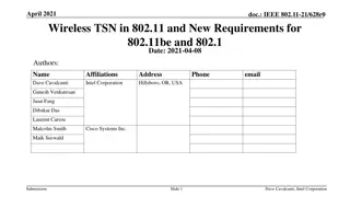
<May 2021> doc.: <15-21-0308-00-0mag> Project: IEEE P802.15 Working Group for Wireless Personal Area Networks (WPANs) Submission Title: [Observations on IEEE Std 802.15.4 timing] Date Submitted: [18 May 2021] Source: [Phil Beecher] Company [Wi-SUN Alliance] Address [Hove Actually, SE England] Voice:[+44-1273-422275], E-Mail:[pbeecher@wi-sun.org] Re: [Observations on 802.15.4 timing.] Abstract: [Observations on 802.15.4 timing] Purpose: [] Notice: discussion and is not binding on the contributing individual(s) or organization(s). The material in this document is subject to change in form and content after further study. The contributor(s) reserve(s) the right to add, amend or withdraw material contained herein. Release: The contributor acknowledges and accepts that this contribution becomes the property of IEEE and may be made publicly available by P802.15. This document has been prepared to assist the IEEE P802.15. It is offered as a basis for Submission Slide 1 <Phil Beecher>, <Wi-SUN Alliance >
<May 2021> doc.: <15-21-0308-00-0mag> Comment submitted at May 2021 Interim 802.15.4 Timing Issues Regarding the timing issues, most of our problems come from the lack of a clear definition in the sequence of delays (and their relationship) taking place in the time interval between consecutive data transmissions, both, delays occurring in the PHY (e.g. turnArounds) and in the MAC (e.g. IFS). First of all, my understanding is that a "turnaround time" is defined as the state transition delay time occurring in two of the PHY state transitions (either Tx->Rx or Rx->Tx). Where turnAround time <= aTurnAroundTime. In the standard, definitions of what constitutes a turnaround are clearly defined (e.g. IEEE 802.15.4-2020 Section 12.3.6), but little to no examples are given of where and when these transitions take place, even less their relationship with some MAC operations like IFS. I attached a simple example figure of the transmission of 2 consecutive data packets in a Non-beacon-enabled mac. (The closest I found to my figure is the Unacknowledged transmission figure in the standard, Figure 6-4) In the Figure, what I would like to know is the time interval between two consecutive transmitted Unacknowledged data packets and the events that form this interval. As shown in the figure, my current understanding is that after the first transmission is completed, the PHY transit from TX to RX and then its MAC proceeds to the IFS followed by the 2 CCA checks and random backoff operations of the CSMA/CA. After the CSMA/CA operations are completed, the PHY transit from RX to TX. Of course, this is just speculation based on some experiments. In my example, I assumed that the PHY transits to Rx immediately after the data transmission is completed because it is possible that a packet is received during the IFS and/or CSMA/CA operations. Could you clarify this sequence of events in the situation presented above? ( turnarounds, IFS,CCA) Does any of these MAC and PHY events overlap? I am aware that in some hardware implementations, IFS and CCA operations overlap to save time (e.g. NXP JN5169) but I am not aware of any other overlaps. I hope this question is clear. Any help you can provide us will help us to make a better implementation of the standard in the ns-3 simulator. Sincerely, (name and address supplied) Submission Slide 2 Slide 2 <Phil Beecher>, <Wi-SUN Alliance >
<May 2021> doc.: <15-21-0308-00-0mag> Timing no ack Interval Between Consecutive Tx Data Packets DATA DATA Random Backoff Delay IFS MAC RX->TX TurnAround TX->RX TurnAround CCA PHY TurnAround <= aTurnAroundTime Total delay time between consecutive unacknowledged data packets in non-beacon enabled mode, O-QPSK TX -> RX Turnaround time = 12 symbols (Table 11-1) CCA duration = 8 symbols (Table 11-1) Submission Slide 3 Slide 3 <Phil Beecher>, <Wi-SUN Alliance >
<May 2021> doc.: <15-21-0308-00-0mag> Timing Ack Interval Between Consecutive Tx Data Packets IMM-ACK DATA DATA Random Backoff Delay IFS AIFS MAC RX->TX TurnAround TX->RX TurnAround CCA PHY TurnAround <= aTurnAroundTime Total delay time between consecutive acknowledged data packets in non-beacon enabled mode, O-QPSK TX -> RX Turnaround time = 12 symbols (Table 11-1) CCA duration = 8 symbols (Table 11-1) Submission Slide 4 Slide 4 <Phil Beecher>, <Wi-SUN Alliance >
<May 2021> doc.: <15-21-0308-00-0mag> 802.15.4-2020 References See Table 11-1 aTurnaroundTime RX-to-TX or TX-to-RX turnaround time (in symbol periods), as defined in 10.2.2 and 10.2.3. -> 12 symbols for OQPSK aCcaTime The time required to perform CCA detection -> 8 symbols of OQPSK See 8.4.2 MAC constants The constants that define the characteristics of the MAC sublayer are presented in Table 8-93. aUnitBackoffPeriod The number of symbols forming the basic time period used by the CSMA-CA algorithm. For all PHYs except SUN PHYs operating in the 920 MHz band, aTurnaroundTime + aCcaTime. For SUN PHYs operating in the 920 MHz band, aTurnaroundTime + phyCcaDuration. See 6.2.5.1 CSMA-CA Algorithm All intervals comprise 20 symbol periods In both cases, the algorithm is implemented using units of time called backoff periods, where one backoff period shall be equal to aUnitBackoffPeriod See10.1.4 Minimum LIFS and SIFS periods For all PHYs other than the HRP UWB PHY, RCC PHY, and SUN OFDM PHY, the minimum LIFS period and SIFS period are as follows: macLifsPeriod: 40 symbols macSifsPeriod: 12 symbols See 6.7.4.3 Acknowledgment The value of AIFS is equal to macSifsPeriod for all other PHYs Submission Slide 5 Slide 5 <Phil Beecher>, <Wi-SUN Alliance >
<May 2021> doc.: <15-21-0308-00-0mag> To do Find references describing event alignment and overlaps Submission Slide 6 Slide 6 <Phil Beecher>, <Wi-SUN Alliance >