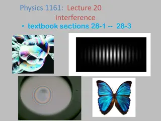
Interference and Diffraction in Light by Dr. Konica Sharma
Explore the fascinating phenomena of interference and diffraction in light, as explained by Dr. Konica Sharma. Learn about constructive and destructive interference, Newton's rings, and experimental arrangements to produce Newton's rings using reflected light.

Download Presentation

Please find below an Image/Link to download the presentation.
The content on the website is provided AS IS for your information and personal use only. It may not be sold, licensed, or shared on other websites without obtaining consent from the author. If you encounter any issues during the download, it is possible that the publisher has removed the file from their server.
You are allowed to download the files provided on this website for personal or commercial use, subject to the condition that they are used lawfully. All files are the property of their respective owners.
The content on the website is provided AS IS for your information and personal use only. It may not be sold, licensed, or shared on other websites without obtaining consent from the author.
E N D
Presentation Transcript
UNIT-I : INTERFERENCE AND DIFFRACTION BY Dr. KONICA SHARMA
INTERFERENCE OF LIGHT: Interference is the phenomenon of the superimposition of one light source over the other. Due to the superimposition of any two light sources, the resultant energy is redistributed into a position of maximum intensity and of minimum intensity. Constructive Interference : If the crest of one wave falls on the crest of the other, constructive interference is produced.
INTERFERENCE OFLIGHT: Destructive Interference : If the crest of one wave falls on the trough of the other, destructive interference is produced. When a soap film or an oil film is viewed from a reflected light or transmitted light, it exhibits different colours. It is due to the interference pattern produced in thin films
NEWTONS RING: CONSTRUCTION : Aplano-convex lens of large radius of curvature is placed with its convex surface in contact with a plane glass plate. Then, an air film is formed between the lower surface of the lens AOB and the upper surface of the plate POQ The thickness of the air film is zero at the point of contact O and gradually increases from the point of contact outwards.
NEWTONS RING: If monochromatic light is allowed to fall normally on this film, a system of alternate bright and dark concentric rings is formed in the air film. They are called Newton's rings.
NEWTONS RING: The thickness of air-film remains constant along a circle with its centre at O. Hence, the fringes are in the form of concentric circles. Newton's rings are formed as a result of interference between the light waves reflected from the upper and lower surface of the air film. 1 and 2 are the interfering rays corresponding to an incident ray SR.
EXPERIMENTALARRANGEMENT: Experimental arrangement for producing Newton s rings by reflected light. S is source of monochromatic light. The light from S rendered parallel rays by a convex lens. These horizontal parallel rays fall on a glass plate G at 45, and are partly reflected from it. This reflected beam falls normally on the lens C placed on the glass plate P
EXPERIMENTALARRANGEMENT: Interference occurs between the rays reflected from the upper and lower surfaces of the film. The interference rings are viewed with a microscope M focused on the air film.
CONDITION FOR BRIGHTAND DARK RINGS: The optical path difference between the rays is since =1 I ntensity maxima =m Bright fringe isobtained I ntensity minima Dark fringe isobtained
RADIIOF DARK FRINGES: Rbe the radiusof curvature of lens Q isthe position of darkfringe Thicknessof air film at Q=PQ=t Radiusof circular fringe at Q be OQ =rm ByPaythagorustheorem PM2=PN2+MN2 2Rt>>t2 Since R>>t
RADIIOF DARK FRINGES: Condition for darkness at Q is: 2t=m Radii of dark fringes ,m=1,2,3, Ring diameter: Diameter of mth dark ring
DETERMINATION OF WAVELENGTH OF SODIUM LIGHTBYNEWTON S RING: Experimental arrangement: Fig. shows an experimental arrangement for producing Newton s rings by reflected light. Sissource of monochromatic light. T he light from Srendered parallel raysby a convex lensL1. T hese horizontal parallel raysfall on a glass plate G at 45, and are partlyreflected from it.
DETERMINATION OF WAVELENGTH OF SODIUM LIGHTBYNEWTON S RING: This reflected beam falls normally on the lens L placed on the glass plate PQ. Interference occurs between the rays reflected from the upper and lower surfaces of the film. The interference rings are viewed with a microscope M focused on the airfilm.
PROCEDURE: With the help of the traveling microscope the diameters of a number of dark rings are measured. The position of the microscope is adjusted to get the centre of Newton's ringsat the point of intersection of the cross-wires. The microscope ismoved until one cross wire istangential to the 16th dark ring. The microscope reading istaken. T hen microscope ismoved such that the cross-wire is successively tangential to 12th, 8thand 4th dark rings respectively. T he readings are noted in each case. Readings corresponding to the same rings are taken on the other side of the centre.
CONT For the (m+p)thring
MICHELSONS INTERFERROMETER: Principle: Here, the two interfering beams are formed by division of amplitude. The amplitude of the lightbeam from an extended source is divided into two parts of equal intensity by partial reflection and refraction. These beams are sent in two perpendicular directions. The two beams are finally brought together after reflection from plane mirrorsto produce interference fringes.
APPARATUS :M1 and M2 are front silvered plane mirrors (The two mirrors are mounted vertically on two arms at right angles to each other. T he planes of the mirrors can be slightly tilted with the fine screws at theirbacks. The mirror M2 isfixed. The mirror M1 can be moved parallel to itself by means of very sensitive micrometer screw. G1 and G2 are two plane parallel glass plates of equal thickness.
APPARATUS The plate G1 is semi silvered on the back side. Gl is a beam splitter; i.e., a beam incident on G1 is partially reflected and partially transmitted. G1 is inclined at an angle of 450to the incident beam. G2 is called the compensating plate. Sis a lightsource.
WORKING: Light from the sources isrendered parallel by a lens Land falls on the glass plate G1 at an angle of 45 . At the back surface of G1, it ispartly reflected along AC and partlytransmitted along AB. The reflected beam moves towards mirror M1 and falls normally on it. Itisreflected back along the same path and emerges out along AT . The transmitted ray AB falls normally on the mirror M2. Itis reflected along the same path. After reflection at the back surface of G1, it moves along AT .T he two emergent beamshave been derived from a single incident beam and are, therefore, coherent. T he two beams produce interference under suitable conditions.
FUNCTION OF G1: T he reflected ray AC passes through G1, thrice But the transmitted ray AB passes through G1, only once. T hat iswhy a second plate G2 of the same thickness and inclination as G1 isintroduced. T hus the function of the plate G1 isonly to equalize the optical paths traversed by both the beams.
CIRCULAR FRINGES: Circular fringes are produced with monochromatic light when mirrorsM1and M2 are exactly perpendicular to beach other. Looking though T M1see directly with virtual image M 2of mirror M2 formed by reflection in G1 Iftwo arms are equal in Length,M 2will coincides with mirror M1
CIRCULAR FRINGES: IfM 2and M1 do not coincides, Then the path difference between the two coherent beams is2d cos . 2dcos + /2 = m where m is an integer. 2dcos is path difference between two beams The condition for a bright ring is
APPLICATIONS OF MICHELSONS INTERFERROMETER: 1) Determination of wavelength of monochromatic light: M1and M2are exactly perpendicular, Circular fringes are obtained IfM1moved forward or backward Circular fringes appear or disappear at the center Now mirrorismoved through known distance d and number of fringes disappear at center iscounted Ifd1initial thickness of air film between M1 and image of M2 corresponding to bright fringe of order m1 d2isfinal thickness of air film corresponding to bright fringe of order mnin same position.
3) THICKNESSOF THINTRANSPARENTSHEET Let transparent sheet of thickness t and RI inserted in path of interfering beam of Michelson s interferometer Optical path increases becomes t instead of t. The increase in optical path is Since beam travels medium twice Extra path difference between two interfering beam is 2(? 1) ? t= Ifm isnumber of fringes by which fringe system isdisplaced 2(? 1) ? =m (?? ?) ?? (? 1) ? ? = ? 2(? 1)
4) DETERMINATIONOF REFRACTIVE INDEXIOF GASES: Ifa tube containing a gas introduced in path of beam going towards M1 Path difference equal to 2(? 1) ? introduced in interfering beams ? isRI of gas and ? islength of tube Ifm fringes cross the center of field of view , 2 ? 1 ? =m ? =? +1 2


 THICKNESSOF THINTRANSPARENTSHEET")
 DETERMINATIONOF REFRACTIVE INDEXIOF GASES:")