Interference Mitigation for Improved Link Adaptation in IEEE 802.11-24
Explore how Interference Mitigation (IM) pilots enhance RX beamforming, analyze benefits of IM scheme on performance and latency, and address concerns related to applying IM pilots. The study delves into Link Adaptation (LA) perspective, showcasing improvements in goodput and Packet Error Rate (PER) with the IM approach.
Download Presentation

Please find below an Image/Link to download the presentation.
The content on the website is provided AS IS for your information and personal use only. It may not be sold, licensed, or shared on other websites without obtaining consent from the author. If you encounter any issues during the download, it is possible that the publisher has removed the file from their server.
You are allowed to download the files provided on this website for personal or commercial use, subject to the condition that they are used lawfully. All files are the property of their respective owners.
The content on the website is provided AS IS for your information and personal use only. It may not be sold, licensed, or shared on other websites without obtaining consent from the author.
E N D
Presentation Transcript
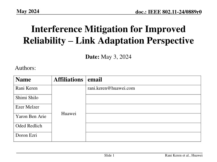
May 2024 doc.: IEEE 802.11-24/0889r0 Interference Mitigation for Improved Reliability Link Adaptation Perspective Date: May 3, 2024 Authors: Name Rani Keren Affiliations email rani.keren@huawei.com Shimi Shilo Ezer Melzer Huawei Yaron Ben Arie Oded Redlich Doron Ezri Slide 1 Rani Keren et al., Huawei
May 2024 doc.: IEEE 802.11-24/0889r0 Introduction In previous contributions [1-4] we proposed a new transmission scheme, in which Interference Mitigation (IM) pilots are inserted within the data field for facilitating RX beamforming in the receiver side, as an efficient approach for interference mitigation. Mitigation of interference can result in improved performance and reduced latency, thus contributing to the ultra high reliability goal of TGbn. In this contribution we analyze this approach from the link adaptation perspective. This analysis addresses some concerns that were recently raised: How do we decide when to apply IM pilots given that we don t know in advance which PPDUs will suffer from interference? Wouldn t we lose significant performance due to the overhead associated with IM pilots? Slide 2 Rani Keren et al., Huawei
May 2024 doc.: IEEE 802.11-24/0889r0 Recap: Interference Mitigation PHY level results Simulation configuration: 4 RX antennas, 1 desired SS transmitted by 1 antenna, 1 interfering SS, SIR=10dB, 106-tone RU, 20% IM pilot subcarriers (20 IM pilot SCs out of 102 data SCs), TGn-D NLOS, 1000 data bytes IM scheme eliminates the PER curves error floors when SNR>SIR, and as a result goodput is significantly improved despite IM pilots overhead. Slide 3 Rani Keren et al., Huawei
May 2024 doc.: IEEE 802.11-24/0889r0 Link Adaptation Perspective We examine the goodput and PER vs. MCS corresponding to the LA search dimension, for a specific channel scenario with SNR=25dB. LA optimization criterion: MCSopt=argmax(Goodput(MCS)). Optional additional constraint: PER < PER_limit due to retransmission s heavier penalty on total throughput. As shown in previous results, the IM scheme significantly improves the maximum goodput in the presence of interference and slightly degrades maximum goodput without an interferer. Slide 4 Rani Keren et al., Huawei
May 2024 doc.: IEEE 802.11-24/0889r0 Random interference activity modeling (1) Presumably, the start and end times of an interferer are random. We use a simplified two-state mixed channel in order to model the random presence or absence of the interferer Independently, per PPDU, we either apply the interference presence or absence channel conditions with probabilities ??and 1 ??, respectively. We test the cases of ??= 0%,10%,25%,50%,75%,100% Note that the IM scheme can mitigate interference that starts and ends anywhere within the PPDU. An example scenario which generates a two-state mixed channel: interference due to spatial reuse. Probability of interference corresponds to the interferer transmission utilization Slide 5 Rani Keren et al., Huawei
May 2024 doc.: IEEE 802.11-24/0889r0 Random interference activity modeling (2) The corresponding PER and Goodput of the mixed channel: We define LA efficiency as the ratio between goodput of a practical LA and a Genie LA that is able to predict the CSI and set the best MCS per PPDU: Slide 6 Rani Keren et al., Huawei
May 2024 doc.: IEEE 802.11-24/0889r0 Link Level results: IM not applied At a certain MCS range, the PER-vs-MCS plots exhibit nearly flat regions with PER level of ~?? since in this region every interfered PPDU is lost. LA experiences a bad tradeoff between maximizing goodput and minimizing PER which forces a penalty of either low goodput or high PER. For ??= 0,10,25,50%, MCSopt=10: interference-free PPDUs are fully utilized but the associated PER is ~ ??. A PER limit restriction could significantly reduce MCSopt and goodput. For ??= 75%, MCSopt=4: avoids loss of interfered PPDUs but doesn t fully utilize the interference-free PPDUs. Nearly flat regions and local maxima in the Goodput-vs-MCS plots may cause issues in the search for maximum goodput. Slide 7 Rani Keren et al., Huawei
May 2024 doc.: IEEE 802.11-24/0889r0 Link Level results: IM applied When IM scheme is applied, interference is mitigated and the LA experiences a well-behaved MCS search space similar to fixed channel conditions. This applies to all ?? cases. Improved maximum goodputs Detailed in following slides. PER-vs-MCS flat regions are eliminated. As a result, PER that corresponds to maximum goodput is relatively low. A good tradeoff between Goodput and PER allows achieving low PER (increased reliability) with low penalty in goodput. Goodput-vs-MCS flat regions are eliminated, enabling efficient search for MCS that maximizes goodput. Slide 8 Rani Keren et al., Huawei
May 2024 doc.: IEEE 802.11-24/0889r0 IM enabled/disabled selection How is the selection between IM enabled and IM disabled carried out? Adaptive approach: Refer to this selection as another dimension in the link adaptation TX parameters search space for goodput maximization along with: MCS, Nss, CP length, etc. Combine IM selection with the ACK guided trial-and-error based search. Example concepts: During IM disabled: Probe a higher MCS along with IM enabled. During IM enabled: Probe current MCS along with IM disabled. For trigger based uplink: The receiving AP can apply on-going and link independent monitoring of interference that can further serve the IM selection decision. Fixed approach: If link reliability is more important than utilizing maximum throughput, IM enabled can be applied as a fixed configuration. Slide 9 Rani Keren et al., Huawei
May 2024 doc.: IEEE 802.11-24/0889r0 Results summary table (No PER limit) Interferer probability 0% 10% 25% 50% 75% 100% Optimum MCS 10 10 10 10 4 4 Goodput in optimum MCS [Mbps] 45.4 40.9 34.1 22.7 16.9 16.1 IM disabled PER in optimum MCS [%] 5 14.5 28.7 52.5 11.8 15.8 Genie LA Goodput [Mbps] 45.4 42.5 38.1 30.8 23.4 16.1 LA efficiency [%] 100 96.2 89.4 73.8 71.9 100 Optimum MCS 10 10 9 9 9 9 Goodput in optimum MCS [Mbps] 36.3 34.1 33 31.9 30.8 29.6 IM enabled PER in optimum MCS [%] 5.7 11.2 3.3 6.7 10 13.3 Genie LA Goodput [Mbps] 36.3 35.6 34.6 32.9 31.3 29.6 LA efficiency [%] 100 95.8 95.5 96.8 98.3 100 IM Goodput gain (fixed) [%] 20.2 - 16.6 - 3.1 - 40.4 82.4 83.8 IM Goodput gain (adaptive) [%] 0 0 0 40.4 82.4 83.8 Slide 10 Rani Keren et al., Huawei
May 2024 doc.: IEEE 802.11-24/0889r0 Results summary table with PER limit (1) PER limit = 20% 0% 10 10% 10 25% 50% 75% 100% Interferer probability 5 4 4 4 Optimum MCS IM Goodput in optimum MCS [Mbps] 45.4 40.9 14.5 10 21.8 14.5 17.6 7.9 16.9 11.8 16.1 15.8 disabled PER in optimum MCS [%] 5 10 9 9 9 9 Optimum MCS IM Goodput in optimum MCS [Mbps] 36.3 5.7 34.1 11.2 33 3.3 31.9 6.7 30.8 10 29.6 13.3 enabled PER in optimum MCS [%] IM Goodput gain (fixed) [%] 20.2 - 16.6 - 51.5 81 82.4 83.8 PER limit = 10% 0% 10 10% 25% 50% 75% 100% Interferer probability 8 4 4 3 3 Optimum MCS IM Goodput in optimum MCS [Mbps] 45.4 34.5 9.9 18.4 3.9 17.6 7.9 12.6 1.1 12.6 1.5 disabled PER in optimum MCS [%] 5 10 9 9 9 9 8 Optimum MCS IM Goodput in optimum MCS [Mbps] 36.3 5.7 33.7 1.3 33 3.3 31.9 6.7 30.8 10 29.5 4.1 enabled PER in optimum MCS [%] IM Goodput gain (fixed) [%] 20.2 - 2.2 - 79.8 81 143.9 134.8 Slide 11 Rani Keren et al., Huawei
May 2024 doc.: IEEE 802.11-24/0889r0 Results summary table with PER limit (2) PER limit = 5% 0% 10 10% 25% 50% 75% 100% Interferer probability 4 4 3 3 3 Optimum MCS IM Goodput in optimum MCS [Mbps] 45.4 18.8 1.6 18.4 3.9 12.7 0.7 12.6 1.1 12.6 1.5 disabled PER in optimum MCS [%] 5 9 9 9 8 8 8 Optimum MCS IM Goodput in optimum MCS [Mbps] 34.2 33.7 1.3 33 3.3 30.1 29.8 29.5 4.1 enabled PER in optimum MCS [%] 0 2 3 IM Goodput gain (fixed) [%] 24.8 - 79.1 79.8 138 136.4 134.8 PER limit = 1% 0% 10% 25% 50% 75% 100% Interferer probability 9 3 3 3 2 2 Optimum MCS IM Goodput in optimum MCS [Mbps] 42.5 0.1 12.7 0.1 12.7 0.4 12.7 0.7 9.6 0.1 9.5 0.2 disabled PER in optimum MCS [%] 9 8 7 7 7 7 Optimum MCS IM Goodput in optimum MCS [Mbps] 34.2 30.6 0.4 25.6 25.6 0.1 25.6 0.1 25.6 0.2 enabled PER in optimum MCS [%] 0 0 IM Goodput gain (fixed) [%] 19.6 - 140.5 101.6 102.3 168 168 Slide 12 Rani Keren et al., Huawei
May 2024 doc.: IEEE 802.11-24/0889r0 Summary IM provides significant goodput gains in interference scenarios IM is very friendly to the link adaptation mechanism in scenarios of randomly varying channel conditions due to interference Allows a low penalty trade-off between maximizing goodput and keeping the PER low. Allows fast convergence to optimal MCS and improved steady state stability. Allows high LA efficiency by fully utilizing channel conditions of interfered PPDU and interference-free PPDUs using the same MCS. The gains of mitigating the interferer are much more significant than the loss due to IM pilots overhead. Slide 13 Rani Keren et al., Huawei
May 2024 doc.: IEEE 802.11-24/0889r0 References [1] 11-23-1490r0: Physical Layer Reliability Improvements (Shimi Shilo et al) [2] 11-23-1943r1: Physical Layer Reliability Improvements Follow Up (Shimi Shilo et al) [3] 11-24-107r0: PHY Layer Interference Mitigation for Improved Reliability (Shimi Shilo et al) [4] 11-24-437r0: Interference Mitigation for Improved Reliability More Insights (Shimi Shilo et al) Slide 14 Rani Keren et al., Huawei


