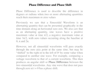
"Explore the theoretical concepts of AC sinusoidal waveforms in electrical engineering. Understand AC circuits with resistive and inductive loads, power calculations, and practical examples for undergraduate and diploma students preparing for exams and competitive tests. Dive into voltage and current relationships, power factor analysis, and more to enhance your understanding of electrical circuits."
Please find below an Image/Link to download the presentation.
The content on the website is provided AS IS for your information and personal use only. It may not be sold, licensed, or shared on other websites without obtaining consent from the author. If you encounter any issues during the download, it is possible that the publisher has removed the file from their server.
You are allowed to download the files provided on this website for personal or commercial use, subject to the condition that they are used lawfully. All files are the property of their respective owners.
The content on the website is provided AS IS for your information and personal use only. It may not be sold, licensed, or shared on other websites without obtaining consent from the author.
CH: Introduction to AC Circuits This Lecture contain Theoretical concept of AC Sinusoidal waveforms with R Load Target audience Beneficial for: Undergraduate and diploma student of all branches for their semester examination. Also helpful for GATE and other competitive exams and Interview.
Average Power Wattmeter average power measured V I V I = m m m m cos2 P t 2 2 = = t I sin sin P vi V t m m V I = (1 cos2 m m ) P t 2
V I V I V I = = m m = P VI m m m m cos2 P t 2 2 2 2 2 V I 1 = (1 cos2 d t m m ) P t 2 2 0 Power factor: 2 2 V I = d t t d t m m 1 cos2 P 4 0 0 V I = m m P 2
Example: A 230V , 50Hz is applied consisting of a pure resistor of 25 . Determine: The current flowing through the circuit Power circuit Equation for instantaneous voltage and current across a circuit absorbed by the
Introduction L Load Voltage applied to pure L di = e Ldt e + = V L = di dt 0 V V = V e = t dt m sin di L di = V Ldt
Voltage applied to pure L V = t dt m sin di L V = t dt m sin i L = 0 sin( 90 ) i I t m ( cos V ) t = m i L V = 0 m L sin( 90 ) i t
Average Power in L = P V i 2 V i 1 = ( sin2 d t m m ) P t = sin( ) sin P V t i t 2 2 m m 2 0 = sin cos P V i t t m m Average Power consumed in full cycle is zero V i = m m sin2 P t 2
Example: A 0.0014H chock coil with negligible resistance is connected to a 220V, 50Hz supply. Determine: Inductive reactance of coil The current flowing through the coil Power consumed by the coil Maximum energy stored in the coil
Average Power in C = P V i 2 V i 1 = d t m m (sin2 ) P t = + sin( ) sin P V t i t 2 2 m m 2 0 = sin cos P V i t t m m Average Power consumed in full cycle is zero Max Energy: V i = m m sin2 P t 2 1 2 = C V 2 W max m
Example: A 318uF Capacitor with is connected to a 200V, Determine: Capacitive reactance offered by capacitor Maximum and rms current Maximum charged on the capacitor Maximum energy stored in the capacitor 50Hz supply. instantaneous
When R-L Load connected to AC supply VL V I VR = + 2 2 V V V V Z R L = I = + 2 2 ( ) ( ) V IR IX L = + 2 2 ( ) R ( ) Z X L = + 2 2 ( ) R ( ) V I X L
When R-L Load connected to AC supply VL V I VR V V I X I R = tan L R X R = = tan L L Z XL X R = 1 tan L R
V i V i = m m m m cos cos(2 ) P t = sin V V t 2 2 m 2 1 = sin( ) i I t = p d t P m 2 0 P V i = V I = m m cos P 2 2 ( ) = sin( ) sin P V t i t m m = cos P V I rms rms V i = m m cos cos(2 ) P t 2
Q factor of coil It is defined as Xl/R or L/R max enegy stored energy dissipated per cycle = (2 ) Q = cos P V I 1LI 2 (I R) T 2 m R Z = = 2 ( ) P IZ I I R = (2 ) Q 2 L( 2 ) 2 2 I fL = = Q 1 f R 2 (I R)
In a circuit consisting of a resistance of 5000 and an inductance of 1.0H in series, a voltage of 150 V at 400Hz Determine: The magnitude and phase of the current and voltage across the resistance and inductance Calculate the power taken by the supply is applied.
Apparent Power: The total power that appear to be transfer between the source and load is called Apparent power True Power (Active Power): The Power which is actually consumed in the circuit. cos P V I = VI Cos R Z VI Sin VI = = 2 ( ) P IZ I I R Reactive apparent power which neither consumed nor does any useful work in the circuit is called reactive power. Power: The component of
Power factor: The factor by which apparent power is multiplied to get actual power is called Power Factor. Z XL R R Z R + = cos R = cos 2 2 L R X Z XC R + = cos 2 2 C R X Z R XL-XC = cos + 2 2 ( ) R X X L c
A current i=14.14sin(t-/6) flows in an electric circuit when a voltage of V=141.4 sin t Determine: The power factor of the circuit. Calculate the value of true power, apparent power and reactive power of the circuit Calculate R,Z, Xl is applied to it.
When R-C Load connected to AC supply V Z = I = + 2 2 ( ) R ( ) Z X C I VR = + 2 2 V V V R C V = + 2 2 ( ) ( ) V IR IX VC C = + 2 2 ( ) R ( ) V I X C
I When R-L Load connected to AC supply VR VC V V V I X I R = C tan R R X R = = C C tan Z XC X R = 1 C tan
V i V i = + m m m m cos cos(2 ) P t = sin V V t 2 2 m 2 1 = + sin( ) i I t = p d t P m 2 0 P V i = V I = m m cos P 2 2 ( ) = sin( ) sin P V t i t m m = cos P V I V i ( ) = + m m 2sin sin( ) P t t 2 V i = + m m cos cos(2 ) P t 2
A voltage of 125v at 60Hz is applied across a resistor connected in series with a condenser. The current in the circuit is 2.2 Amp and power loss in the resistor is 96.8 watt and that of condenser Determine: The capacitance is negligible resistance and


")